
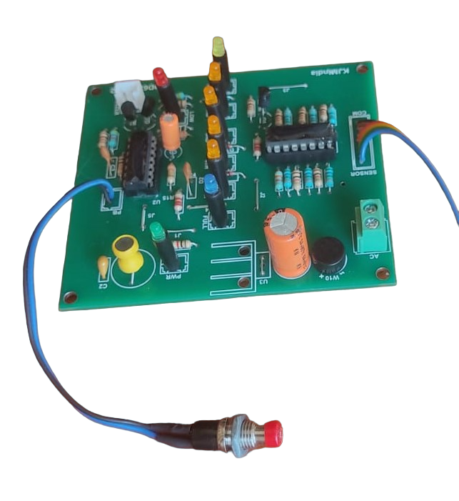
Zero Corrosion Water Level Indicator Circuit | Full & Low Alarm
Understanding Electrolysis in Water Level Controller Circuits
Many DIY and commercial water level sensing and control circuits are available on the internet. Most of these low-cost designs use metal probes as water sensors. While simple and affordable, they have one major drawback — electrolysis.
On the other hand, circuits that use float switches, ultrasonic sensors, or magnetic reed sensors do not suffer from electrolysis. However, they are relatively costly compared to circuits that use direct metal probes.
It’s also important to note that pure water is a poor conductor of electricity. This means that in 100% pure water, a probe-based water level sensing circuit will not work at all.
🔍 What is Electrolysis?
Electrolysis is the chemical process of breaking down a substance using an electric current. In simple terms, it involves passing electricity through a liquid or molten substance that contains positive (cations) and negative (anions) ions.
- Two electrodes (metal rods) are dipped into the liquid.
- These electrodes are connected to a power source such as a battery or DC supply.
- The electrode connected to the positive terminal becomes the anode and attracts negative ions.
- The electrode connected to the negative terminal becomes the cathode and attracts positive ions.
This movement of ions causes chemical reactions at the electrodes, which can lead to corrosion, gas formation, or deposits in the water.
⚡ Does Electrolysis Occur in AC and DC?
A common misconception is that electrolysis only occurs in DC circuits. The truth is:
- DC Circuits → Electrolysis occurs continuously because the current always flows in one direction. This leads to faster electrode wear and more noticeable chemical reactions.
- AC Circuits → Electrolysis also takes place, but at a much slower rate. This is because the polarity of the electrodes keeps reversing every half cycle, causing the reactions to partially cancel each other out. However, over time, cloudiness and deposits still appear in the water.
👉 This is why AC-based water level controller circuits with probes still experience some level of electrode degradation, though not as fast as DC-based ones.
You can test the electrolysis in AC using the following method:
Parts Required:
- A bowl of water with some salt dissolved in it
- 2 copper wires used as electrodes.
- 9v or 12v stepdown transformer
🛠️ Steps to Perform the Experiment
1️⃣ Connect the transformer: Attach the primary of the step-down transformer to the 230V AC supply 🔌.
2️⃣ Attach the electrodes: Connect the electrodes to the secondary of the transformer ⚡.
3️⃣ Prepare the salt water: Fill a bowl with water 💧 and mix in some salt 🧂.
4️⃣ Insert electrodes: Place the electrodes carefully inside the bowl 🥣.
5️⃣ Turn on the power: Switch on the transformer 🔋 and observe.
6️⃣ Notice the reaction: Tiny bubbles 🫧 will start sticking to both electrodes, showing that electrolysis is happening ✨.
💡 Why Add Salt?
In pure drinking water 🚰, the reaction is very weak and hard to see. Adding salt 🧂 increases the conductivity, making the electrolysis process much clearer and more visible 👀.
✅ Key Takeaways
- Electrolysis occurs only when the electrode voltage is above the electrolysis threshold (around 1.23 V for water).
- In conventional DC probe circuits (5 V–12 V), electrolysis is strong, leading to probe corrosion and water contamination.
- In conventional DC probe circuits (5 V–12 V), electrolysis is strong and causes electrode corrosion.
- In AC probe circuits, electrolysis is slower but not eliminated, since polarity reversal only reduces the net effect.
- With a specially designed low-voltage DC sensing circuit (<1.23 V), electrolysis can be completely avoided.
Click here to view the circuit
You should also read:
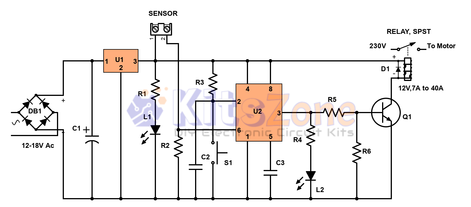
Semi-Automatic Water Level Controller Circuit Using 555 Timer
Managing water efficiently is crucial to avoid wastage and overflow 🚰. A semi-automatic water level controller circuit using a 555 timer IC provides a simple yet effective solution for controlling water pumps. This project not only prevents tank overflow but also reduces manual effort. By using a 555…
Continue reading...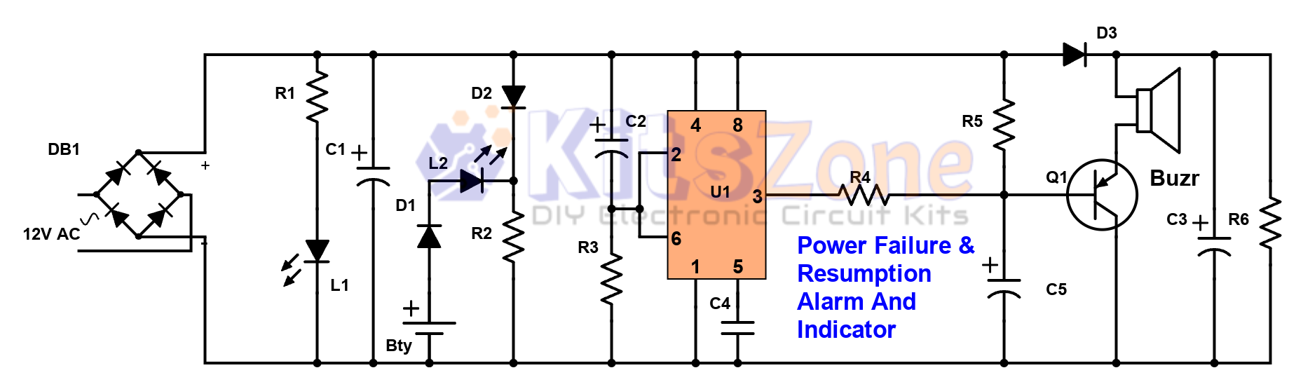
Power Failure and Resumption Alarm Circuit using 555 IC
⚡ Power cuts can cause inconvenience, equipment damage, and even safety risks. That’s why a Power Failure and Resumption Alarm Circuit using 555 Timer IC is a simple yet powerful solution! This DIY electronics project not only alerts you when electricity goes off but also notifies you…
Continue reading...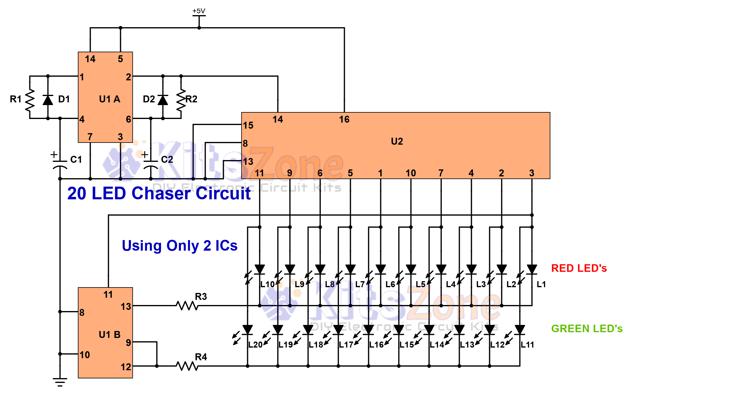
Light Chaser Circuit Using Cd4017 And Cd4013
Looking for a fun and easy electronics project? 🤔 A 20 LED chaser circuit Using Cd4017 And Cd4013 is a perfect DIY project for beginners and hobbyists. Instead of the commonly used 555 timer, this project uses CD4017 (decade counter IC) and CD4013 (dual flip-flop IC) to create a smooth light…
Continue reading...