
Water Level Indicator Circuit With IC 555 | Dry Run Alarm
Managing water at home or in industries is a challenge. Many times, motors run dry, water tanks overflow, or pumps are left on longer than needed. This Water Level Indicator Circuit with IC 555 solves all those problems. It is a low-cost, easy-to-build project that shows water levels with LEDs and sounds alarms for different conditions. Click here for a zero electrolysis water level indicator circuit.
This DIY water level indicator circuit with IC 555 project is perfect for beginners, students, or anyone who wants to save water, electricity, and protect their water pump from damage.
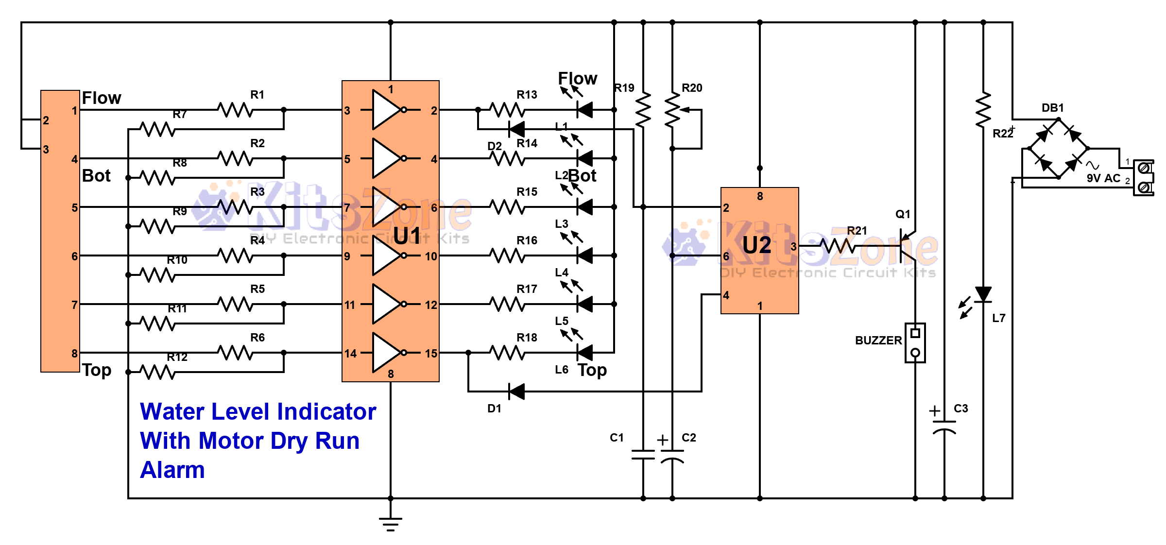
Circuit Diagram

Parts Required
Resistors (All 1/4W)
- R1 – R6 – 1M
- R7 – R12 – 220K
- R13 – R17 – 1K
- R18 – 3.3K
- R19 – 1M
- R20 – 100K (Preset)
- R21 – 1K
- R22 – 1.5K
Capacitors
- 104 (0.1uF) – Ceramic Disc – 1 pc
- 100uF, 25V – 1 pc
- 470uF, 40V – 1 pc
Integrated Circuits (ICs)
- U1 – CD4049 (with base)
- U2 – 555 Timer IC (with base)
Diodes
- D1 – LED
- D2 & D3 – IN4148
- DB1 – W04 Bridge Rectifier
Transistor
- S8550 PNP
Connectors & Transformer
- Relimate Connector (8 Pin Sensor + 6 Pin LED – optional)
- Transformer: 9V, 500mA – 1A
- (If using 7812 voltage regulator, you can use a 15V or 18V transformer)
Others
- 2-pin terminal block connector
- 12V DC buzzer
Features of This Water Level Circuit
✔️ Low cost & low power consumption
✔️ No microcontroller required – no coding needed
✔️ 6 levels of water indication (3, 4, or 5 levels also possible)
✔️ Motor dry-run protection – alarm when no water is available
✔️ Overflow protection – alarm when tank is full
✔️ Flow detection – alerts if water stops filling midway
✔️ Built with easily available components
✔️ Less electrolysis & longer life. Click here to view the zero electrolysis circuit.
Benefits of this Water Level Indicator Circuit
💧 Saves water – prevents overflow
⚡ Saves electricity – no unnecessary motor running
🕒 Saves time – check tank levels without climbing upstairs
🛡 Protects the motor – avoids dry running damage
✅ Convenient – monitor water levels from one place
How the Circuit Works
- Power Supply – A bridge rectifier (DB1) converts AC to DC.
- Tank Empty Condition – When the tank is empty, the circuit waits for water flow. If no water enters within the set time (adjustable via R20), an alarm sounds.
- Water Flow Detected – If water enters, LEDs indicate rising water levels.
- Water Stops Midway – Alarm sounds if flow stops before reaching the top.
- Tank Full – Once water reaches the top sensor, the buzzer alerts you to turn off the motor.
- The CD4049 IC works as a level detector.
- The 555 Timer IC generates alarms for different conditions.
- LEDs show real-time water levels.
Modes of Operation
This single kit can be used in multiple ways:
- As an Overflow Indicator
- As Low + High Level Indicator
- As 3 / 4 / 5 / 6 Level Indicator
- As a Water Flow Alarm
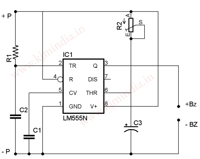
Auto Cut-off for Overflow Alarm
Normally, the buzzer keeps ringing until you switch it off. With a simple modification, you can add auto cut-off so that the alarm stops after a few seconds or minutes. The cut-off time is set using a preset resistor.
Instead of connecting the buzzer directly to the output, it can be connected via the circuit shown at the top. Connect the positive wire (brown wire) to +P and negative wire to -P (black wire)
Extra Components Needed for Auto Cutoff:
- Capacitors: 0.1uF (C1, C2), 100uF (C3)
- Resistors: 1M (R1), 1M preset (R2)
- IC: 555 Timer
- Buzzer: 12V DC
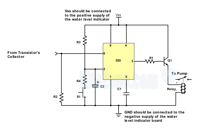
Convert Into a Semi-Automatic Water Level Controller
By making a small change, this indicator can also control your water pump.
- Add a momentary switch (S1) to start the pump.
- Once the tank is full, the pump will stop automatically.
- Works with a 12V relay to handle pump power.
Extra Components Needed:
- Resistors: 1k, 100k ×2
- Capacitors: 0.01uF, 10uF/25V
- Transistor: 8050 NPN
- Relay: 12V, 20A–30A
Frequently Asked Questions (FAQ)
👉 Yes. Just remove the preset or short sensor pins 1 and 2.
👉 Yes. By adding the auto cut-off circuit, the alarm stops after a set time.
👉 Yes. With a relay and minor modifications, it can turn into a semi-automatic water level controller.
👉 Use 9V, 500mA–1A transformer. If using 15V or 18V, add a 7812 regulator IC. or you can use a light weight 12v smps modules readily available online.
👉 Copper, aluminium, stainless steel wires, or even magnetic float switches. Click here for a zero electrolysis water level indicator circuit.
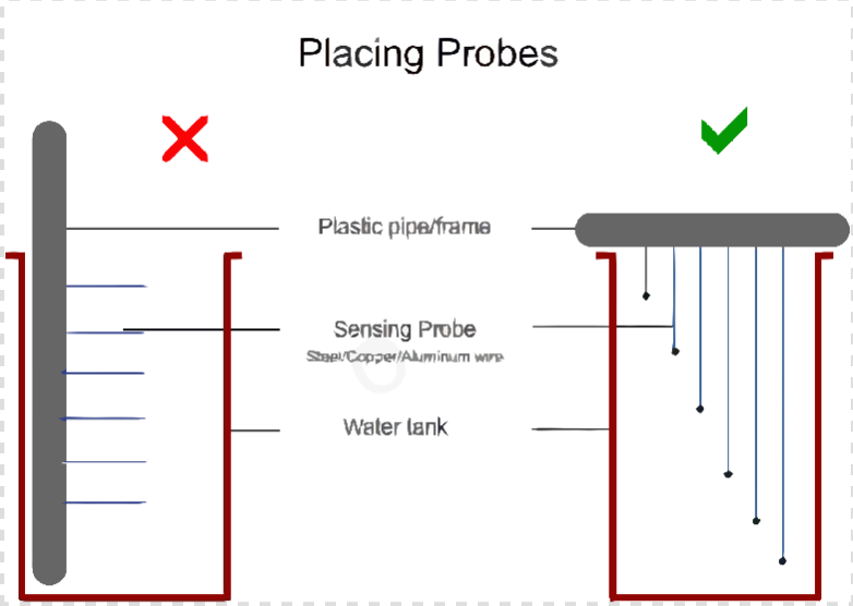
Placing the Probes (Sensors)
- Use copper, aluminium, or stainless-steel wires as probes.
- Keep them at different water levels inside the tank.
- Clean them once a year to remove dirt deposits.
- Make sure probes don’t touch the tank walls or each other.
Connection Details of IC 555 water level indicator project
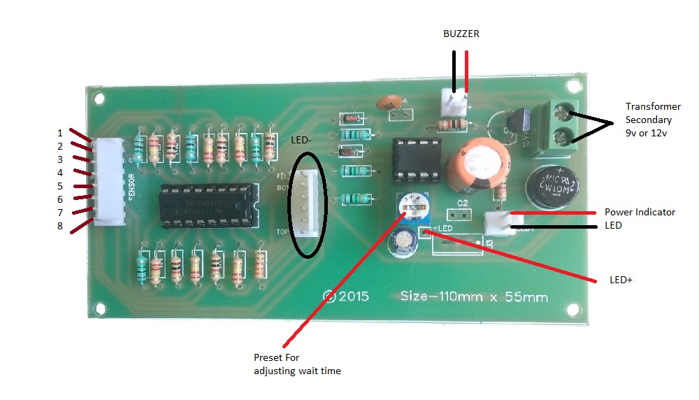
| Sensor Pin | Function | Details |
|---|---|---|
| 1 F(L) | Water Flow Sensing | Used for flow sensing in overhead tank (OHT) or low water sensing in sump. |
| 2 +ve Supply | Water Flow Sensing | Works along with pin 1 for flow sensing. |
| 3 +ve Supply | Inside Tank | Placed inside the tank but must not touch the bottom. |
| 4 | First Level | Indicates first water level. |
| 5 | Second Level | Indicates second water level. |
| 6 | Third Level | Indicates third water level. |
| 7 | Fourth Level | Indicates fourth water level. |
| 8 – Top Level | Tank Full | Indicates top water level (overflow alarm). |
👉 Note: Pins 1 and 2 together are used for water flow sensing in the OHT or for low-level detection inside the sump.
🔹 LED Connections of IC 555 water level indicator project
The negative terminals of all six LEDs should be connected to LED-. Next, link the positive terminals to LED+, making sure that all positive pins are shorted together. This setup ensures proper level indication.
🔹 Buzzer Connection
For the buzzer, connect it with the correct polarity — the brown wire goes to positive (+) and the black wire to negative (–). Double-check the wiring to avoid reverse connection.
🔹 Sensor Wiring
You can use 8-colour flat ribbon wire or a CAT-6 cable to connect the sensor in the tank to the indicator unit. For probes, materials like copper, aluminium, stainless steel wires, or magnetic float switches work best.
Working Video
You should also read:
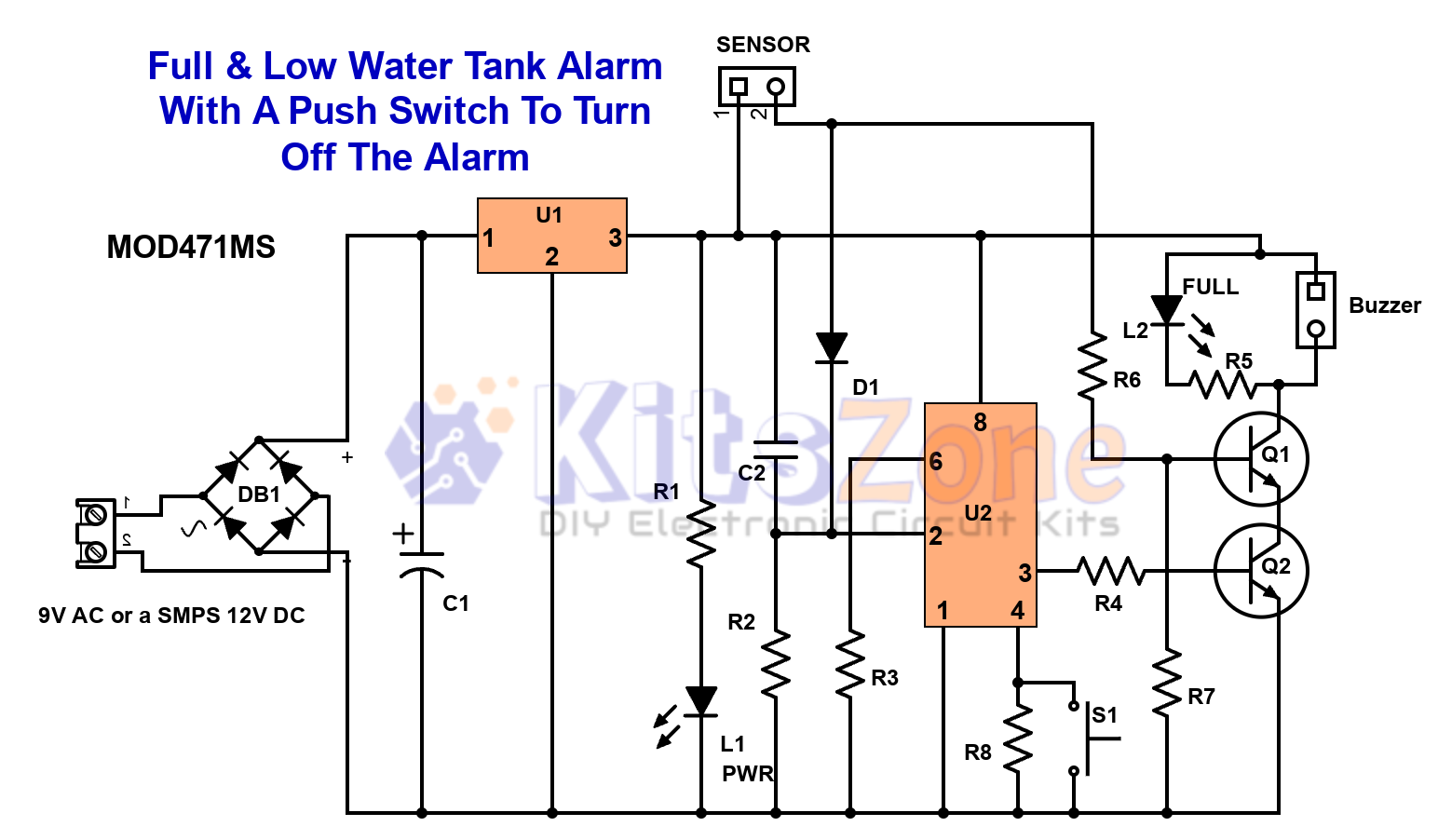
Full & Low Water Tank Alarm Circuit Using 555 Timer Ic
💧 Are you tired of water overflowing from your overhead tank or running out of water at the wrong time? A Full & Low Water Tank Alarm Circuit using 555 Timer IC is the perfect DIY solution to ensure efficient water management. This smart circuit not only…
Continue reading...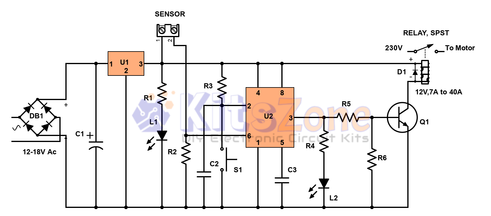
Semi-Automatic Water Level Controller Circuit Using 555 Timer
Managing water efficiently is crucial to avoid wastage and overflow 🚰. A semi-automatic water level controller circuit using a 555 timer IC provides a simple yet effective solution for controlling water pumps. This project not only prevents tank overflow but also reduces manual effort. By using a 555…
Continue reading...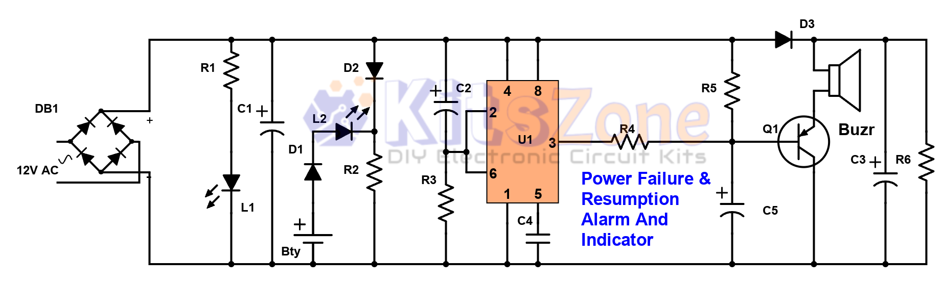
Power Failure and Resumption Alarm Circuit using 555 IC
⚡ Power cuts can cause inconvenience, equipment damage, and even safety risks. That’s why a Power Failure and Resumption Alarm Circuit using 555 Timer IC is a simple yet powerful solution! This DIY electronics project not only alerts you when electricity goes off but also notifies you…
Continue reading...