
Water Level Indicator Circuit With Full And Empty Tank Alarm | Upto 7 Levels

Introduction
Managing an overhead water tank manually is inconvenient and often leads to overflow or unnoticed empty tank conditions. This Water Level Indicator Circuit provides a reliable and practical solution by offering up to 7 levels of visual indication along with dedicated full and low tank alarms. Continuous tone for full tank and intermittent beep for empty tank (Dual tone).
The design uses only standard analog ICs and discrete components — no microcontrollers, no programming, and no firmware dependency. It is easy to build, simple to service, and ideal for residential or small commercial applications.
✨ Key Features
✔ Upto 7 levels of water indication
✔ Continuous tone alarm for full tank
✔ Intermittent beep alarm for low tank
✔ Option to enable full alarm, low alarm, or both
✔ Push button to mute the alarm. No need to manually turn on or off the switch.
✔ Low LED continues blinking even after muting
✔ Built using readily available components
✔ No microcontroller – no programming required
✔ Easy to troubleshoot and service
📐 Circuit Diagram
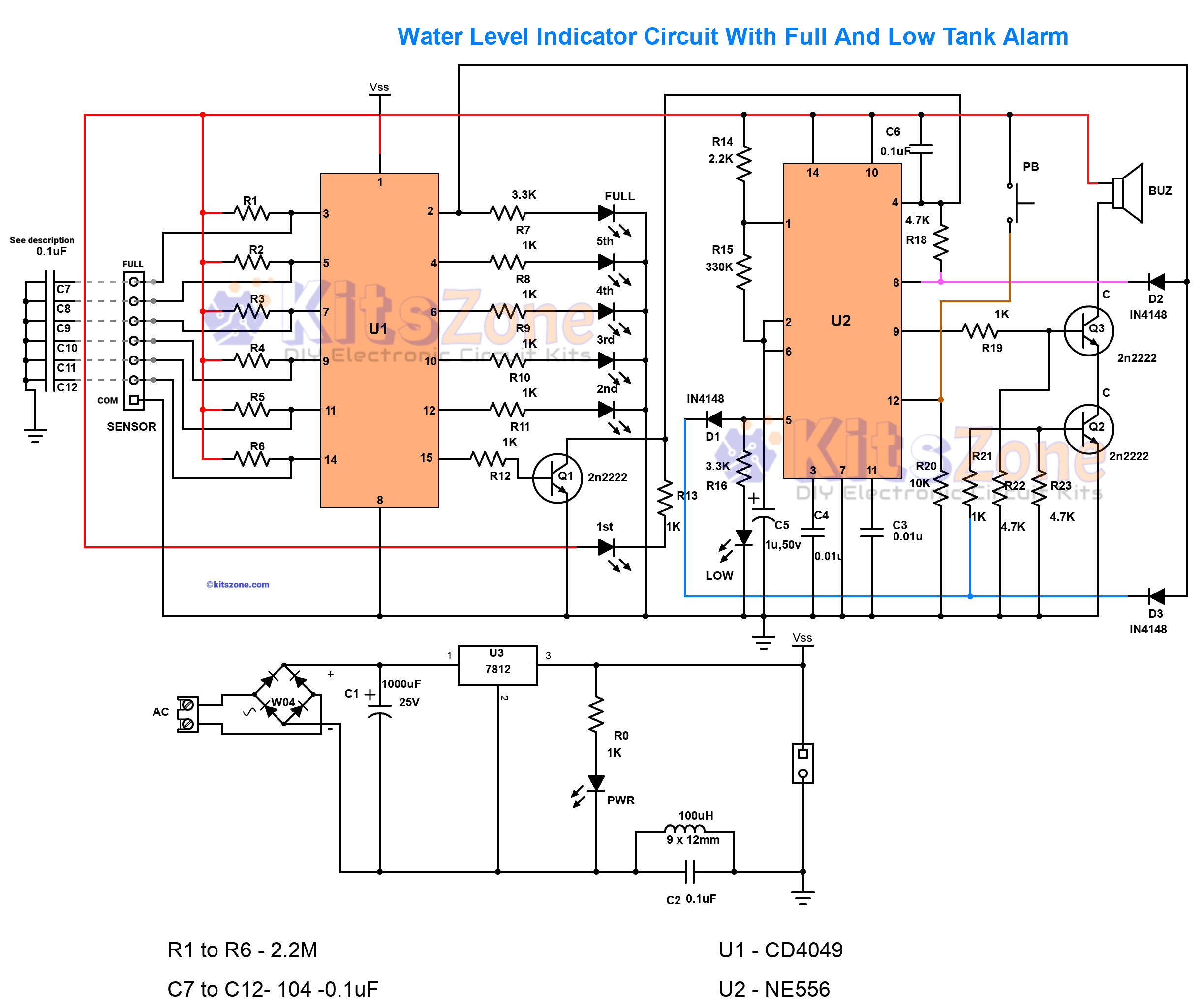
The circuit consists of three main sections:
Level detection using inverter IC
Alarm generation using dual timer IC
Regulated power supply section
🧰 Parts Required
Resistors (All 1/4 Watt)
R1 to R6 – 1M
R7 – 3.3K
R8 to R13, R19, R21 – 1K
R14 – 2.2K
R15 – 330K
R16 – 3.3K
There is no R17
R18, R22, R23 – 4.7K
R20 – 10K
Capacitors
C1 – 1000µF, 25V
C2, C6 – 0.1µF, ceramic
C3, C4 – 0.01µF, ceramic
C5 – 1µF, 25V
C7 to C12 – 0.1µF (optional, for long cable interference reduction)
Diodes
Bridge Rectifier – DB107 or W04
(or 4 × 1N4007 diodes)
D1, D2, D3 – 1N4148
Transistors
Q1, Q2, Q3 – 2N2222
ICs
U1 – CD4049
U2 – NE556
U3 – 7812
(Not required if using 9V transformer,12V SMPS or 9/12v battery. Short pin 1 and 3 in the voltage regulator section of the Pcb.)
Miscellaneous
>3 - 15v continuous tone Buzzer
>Push Button Switch (PB)
>LEDs
>100µH Inductor (optional for power line disturbance reduction)
>Water level probes
⚙ Circuit Working
1. Water Level Detection
The CD4049 inverter IC senses water through stainless steel probes placed at different heights inside the tank. As water touches each probe, a signal is generated and corresponding LEDs turn ON to indicate the level.
The circuit can display up to 7 levels depending on the number of probes used.
2. Full Tank Alarm
When water reaches the topmost probe:
The full-level LED turns ON
The NE556 timer generates a continuous tone
The buzzer sounds continuously
This alerts the user to stop filling the tank.
3. Low Tank Alarm
When water drops below the minimum probe:
Low LED turns ON
NE556 generates an intermittent beep
Buzzer sounds periodically
Even if the push button is pressed to mute the alarm, the Low LED continues blinking as a visual reminder.
4. Alarm Mute Function
The push button allows temporary silencing of the buzzer without affecting level indication.
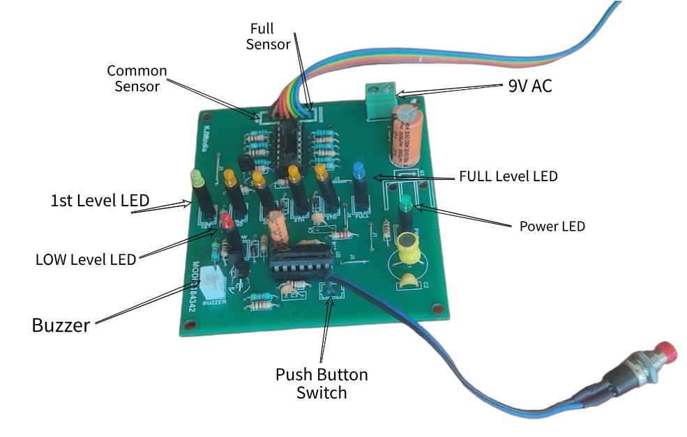
🧪 Prototype Module
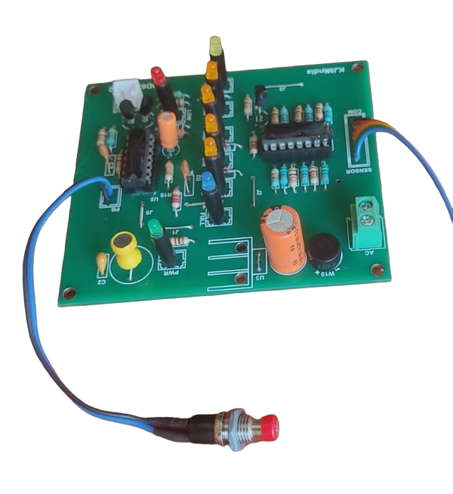
The circuit was initially tested on a breeadboard and later tested on a professionally designed PCB using short probe wires. After verification:
Level transitions were stable
Full alarm generated continuous tone
Low alarm produced intermittent beep
Mute function operated correctly
Optional capacitors (C7–C12) were tested for long cable setups and effectively reduced interference.
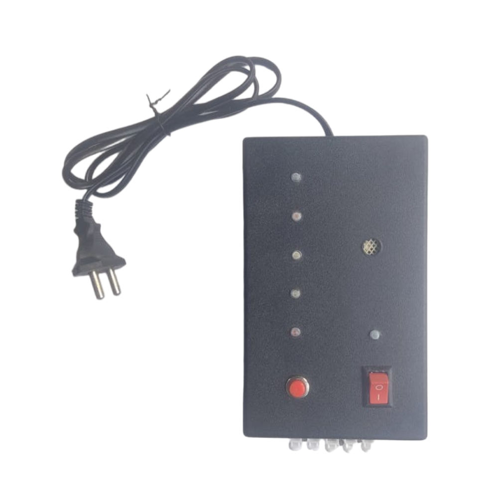
🏁 Fully Finished Prototype
🎬 Working Video
Watch the complete demonstration below:
The video shows:
Level LED transition
Full tank alarm
Low tank alarm
Push button mute function
🛡 Zero Corrosion Design
One of the major problems in water level indicators is probe corrosion due to continuous DC current(electrolysis).
Understanding Electrolysis in Water Level Controller Circuits
Many DIY and commercial water level sensing and control circuits are available on the internet. Most of these low-cost designs use metal probes as water sensors. While simple and affordable, they have one major drawback — electrolysis.
On the other hand, circuits that use float switches, ultrasonic sensors, or magnetic reed sensors do not suffer from electrolysis. However, they are relatively costly compared to circuits that use direct metal probes.
It’s also important to note that pure water is a poor conductor of electricity. This means that in 100% pure water, a probe-based water level sensing circuit will not work at all.
🔍 What is Electrolysis?
Electrolysis is the chemical process of breaking down a substance using an electric current. In simple terms, it involves passing electricity through a liquid or molten substance that contains positive (cations) and negative (anions) ions.
- Two electrodes (metal rods) are dipped into the liquid.
- These electrodes are connected to a power source such as a battery or DC supply.
- The electrode connected to the positive terminal becomes the anode and attracts negative ions.
- The electrode connected to the negative terminal becomes the cathode and attracts positive ions.
This movement of ions causes chemical reactions at the electrodes, which can lead to corrosion, gas formation, or deposits in the water.
⚡ Does Electrolysis Occur in AC and DC?
A common misconception is that electrolysis only occurs in DC circuits. The truth is:
- DC Circuits → Electrolysis occurs continuously because the current always flows in one direction. This leads to faster electrode wear and more noticeable chemical reactions.
- AC Circuits → Electrolysis also takes place, but at a much slower rate. This is because the polarity of the electrodes keeps reversing every half cycle, causing the reactions to partially cancel each other out. However, over time, cloudiness and deposits still appear in the water.
👉 This is why AC-based water level controller circuits with probes still experience some level of electrode degradation, though not as fast as DC-based ones.
You can test the electrolysis in AC using the following method:
Parts Required:
- A bowl of water with some salt dissolved in it (to speed up the reaction)
- 2 copper wires used as electrodes.
- 9v or 12v stepdown transformer
🛠️ Steps to Perform the Experiment
1️⃣ Connect the transformer: Attach the primary of the step-down transformer to the 230V AC supply 🔌.
2️⃣ Attach the electrodes: Connect the electrodes to the secondary of the transformer ⚡.
3️⃣ Prepare the salt water: Fill a bowl with water 💧 and mix in some salt 🧂.
4️⃣ Insert electrodes: Place the electrodes carefully inside the bowl 🥣.
5️⃣ Turn on the power: Switch on the transformer 🔋 and observe.
6️⃣ Notice the reaction: Tiny bubbles 🫧 will start sticking to both electrodes, showing that electrolysis is happening ✨.
💡 Why Add Salt?
In pure drinking water 🚰, the reaction is very weak and hard to see. Adding salt 🧂 increases the conductivity, making the electrolysis process much clearer and more visible 👀.
✅ Key Takeaways
- Electrolysis occurs only when the electrode voltage is above the electrolysis threshold (around 1.23 V for water).
- In conventional DC probe circuits (5 V–12 V), electrolysis is strong, leading to probe corrosion and water contamination.
- In conventional DC probe circuits (5 V–12 V), electrolysis is strong and causes electrode corrosion.
- In AC probe circuits, electrolysis is slower but not eliminated, since polarity reversal only reduces the net effect.
- With a specially designed low-voltage DC sensing circuit (<1.23 V), electrolysis can be completely avoided.
We can convert this circuit to minimize corrosion by:
Using very high value resistors (2.2MΩ for R1 to R6)
This allows extremely small sensing current
Thus reducing electrolysis effect on probes
This significantly increases probe life and ensures long-term reliability.
🛒 PCB Available – Order Now
❓ FAQ – Water Level Indicator
1. Can this circuit work with plastic water tanks?
Yes. The probes are placed inside the tank and detect water directly. Please refer the placing probes section on how to place the probes.
2. What is the maximum cable length supported?
For long cables, use shielded wires and install C7–C12 capacitors to prevent interference while using 2.2M for R1 to R6. I have tested up-to 90 meters.
3. Can I increase the number of levels?
Yes. The design supports up to 7 levels depending on probe configuration. For more levels just cascade the inverter IC.
4. Does this protect the motor from dry run?
No. This circuit only indicates tank level and gives alarms.
5. Can I disable only the low or empty alarm?
Yes. Alarm sections can be configured depending on requirement. Just remove the diode D1 (IN4148) to disable the empty tank alarm.
6. What power supply is required?
12V SMPS supply, 9V transformer or 9v/12v battery can be used to power this circuit.
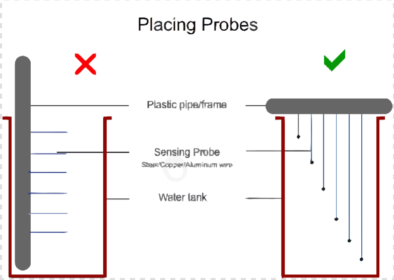
Note: "C" marked in the sensor part is the common. Above common are 1 to 6 levels.
"C" should be suspended to the bottom of the water tank but it should not touch the bottom or sides of the tank.
All the metal sensors should be suspended vertically without touching each other or the sides of the water tank.
0.1uf ceramic disc capacitor is mandatory in order to avoid wrong indications due to capacitive coupling on using long cables.
We can use 3 core to 8 core cable as per our requirement. Twisted pair cables are recommended. The connection point of the sensors and cable should be well insulated and should be weather proof.
Placing Probes
📌 Conclusion
This Water Level Indicator Circuit provides a practical, service-friendly, and reliable solution for monitoring overhead tank levels. With up to 7 levels of indication and dedicated full and low alarms, it ensures better water management without complex programming.
Its zero-corrosion design and simple architecture make it suitable for long-term real-world use.
You should also read:
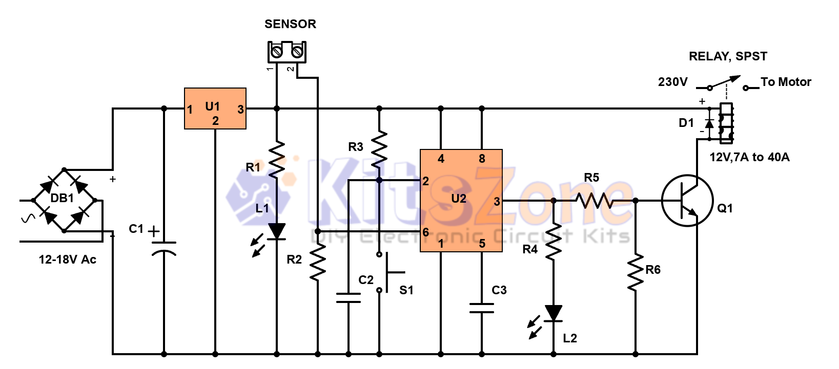
Semi-Automatic Water Level Controller Circuit Using 555 Timer
Managing water efficiently is crucial to avoid wastage and overflow 🚰. A semi-automatic water level controller circuit using a 555 timer IC provides a simple yet effective solution for controlling water pumps. This project not only prevents tank overflow but also reduces manual effort. By using a 555…
Continue reading...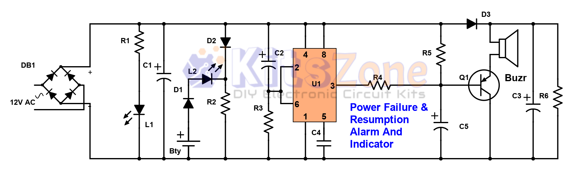
Power Failure and Resumption Alarm Circuit using 555 IC
⚡ Power cuts can cause inconvenience, equipment damage, and even safety risks. That’s why a Power Failure and Resumption Alarm Circuit using 555 Timer IC is a simple yet powerful solution! This DIY electronics project not only alerts you when electricity goes off but also notifies you…
Continue reading...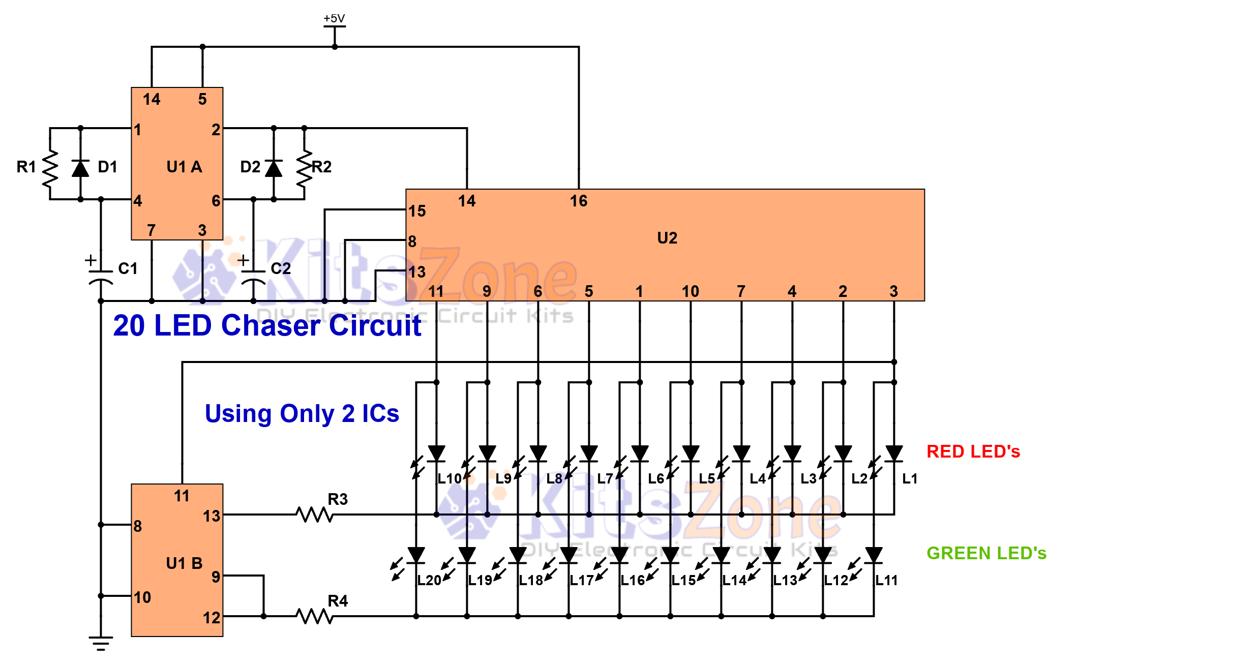
Light Chaser Circuit Using Cd4017 And Cd4013
Looking for a fun and easy electronics project? 🤔 A 20 LED chaser circuit Using Cd4017 And Cd4013 is a perfect DIY project for beginners and hobbyists. Instead of the commonly used 555 timer, this project uses CD4017 (decade counter IC) and CD4013 (dual flip-flop IC) to create a smooth light…
Continue reading...