
Water Level Controller Circuit With Motor Dry Run Protection

Managing water levels in overhead tanks and reservoirs is no longer a hassle! ✅ An automatic water level controller ensures your pump operates only when needed, saving water, electricity, and preventing motor damage.
This water level controller circuit with motor dry run protection uses a float switch and dual timer IC (556) to monitor water levels, automatically switching the
motor ON when the water level is low and OFF when the tank is full. It also protects your mono-block pump from running dry when there is no water in the sump/well. 💧⚙️
Perfect for homes, apartments, and industries, this circuit provides fully automatic and semi-automatic control with manual ON/OFF switches, ensuring complete flexibility. Click here to buy the readymade kit
🌟 Features of This Circuit
- 💡 Low-cost circuit using easily available components
- 🔋 Low power consumption
- 🛑 Turns OFF pump when the tank is full
- 💧 Turns ON pump when water level is low
- 🚱 Motor dry run protection (no water in sump = motor OFF)
- ⚡ Auto restart after power failure
- 🧑💻 Regular ICs are used so no programming knowledge required.
- 🏠 Compact design – suitable for up to 3HP motors
- 🔘 Manual & Auto mode available
- 🔴 Indicator LEDs for Top, Bottom, Flow, Power & Motor status
🛠️ Parts Required
Resistors (¼ Watt)
- R1, R4, R5, R10, R11 – 4.7K
- R9, R13 – 2.2K
- R3 – 1M Preset
- R2, R14 – 10K
- R6, R7 – 470K (Use 1M if you want to use SS metal sensors instead of float switches)
- R8 – 33K
- R12 – 18K
Capacitors
- C1, C5 – 100µF, 50V
- C2, C3, C4, C7, C8, C13 – 0.1µF disc (104)
- C6 – 0.01µF disc (103)
Inductor
- L1 – 100µH, 1A
LEDs (3mm/5mm)
- L2 – Power
- L3 – Top
- L4 – Bottom
- L5 – Flow
- L6 – Motor
Diodes
- D1, D2, D4 – IN4148
- D3 – IN4007
- Bridge Rectifier DB1 – W04
Transistors
- Q1 – BC547
- Q2 – 2N2222
Update: (20-02-2025)
Change Q1 to BC517 Transistor, R9 to 2.2M & R14 to 2.7M to reduce electrolysis in dry run sensor. You can try with different values of R9 & R14 in order to completely avoid electrolysis.
ICs
- U1 – 7812 with T220 Heat Sink
- U2 – 556 Dual Timer
Others
- Relay: 12V, 30A/40A
- Transformer: 12V–18V, 1A
- Float Switch: Vertical or Horizontal
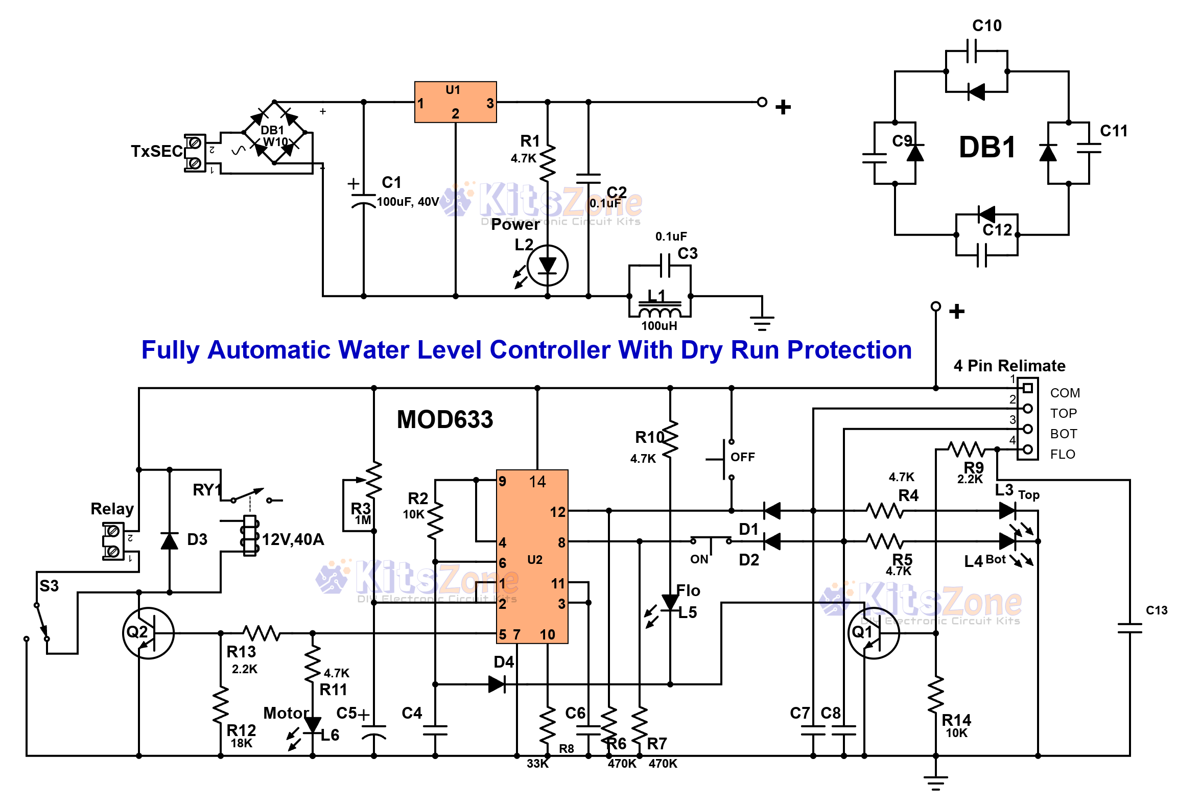
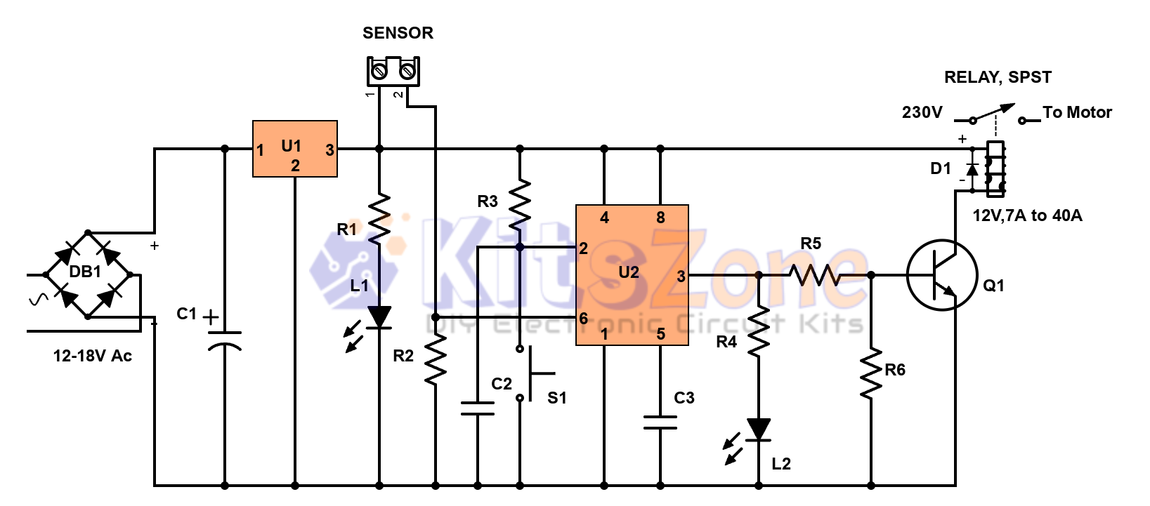
⚙️ Working of the Circuit
- 🔌 AC voltage from the transformer (12–18V) is rectified by DB1 and filtered by C1.
- ⚡ The regulated DC supply powers the 556 dual timer IC.
- 📊 Float switches detect top and bottom water levels, sending signals to the timer IC.
- 🔄 Pump automatically starts when the water level goes below the bottom float.
- 🛑 Pump stops when water reaches the top float or when dry run (no water flow) is detected.
- 🔘 Manual ON/OFF switches allow user control within safe water levels.
- 🏷️ LEDs indicate Power, Motor ON, Top, Bottom, and Flow status for easy monitoring.
If water flow is not detected within the set delay (adjustable via preset R3), the circuit shuts down the motor to prevent damage.
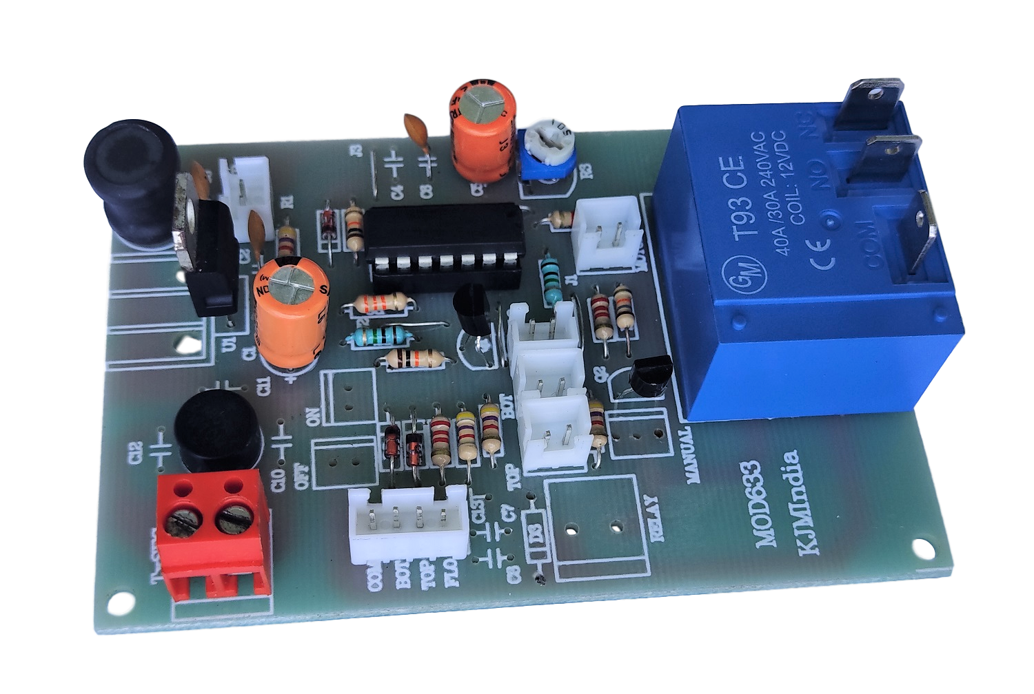
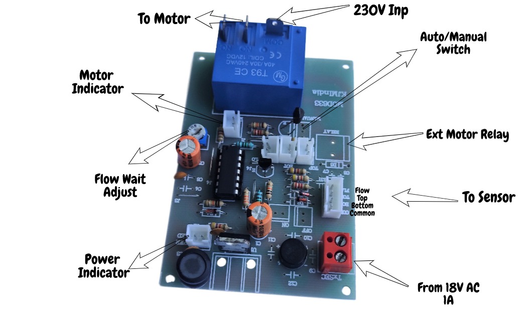
Water Level Controller Readymade Kit
Water Level Controller Connection Details
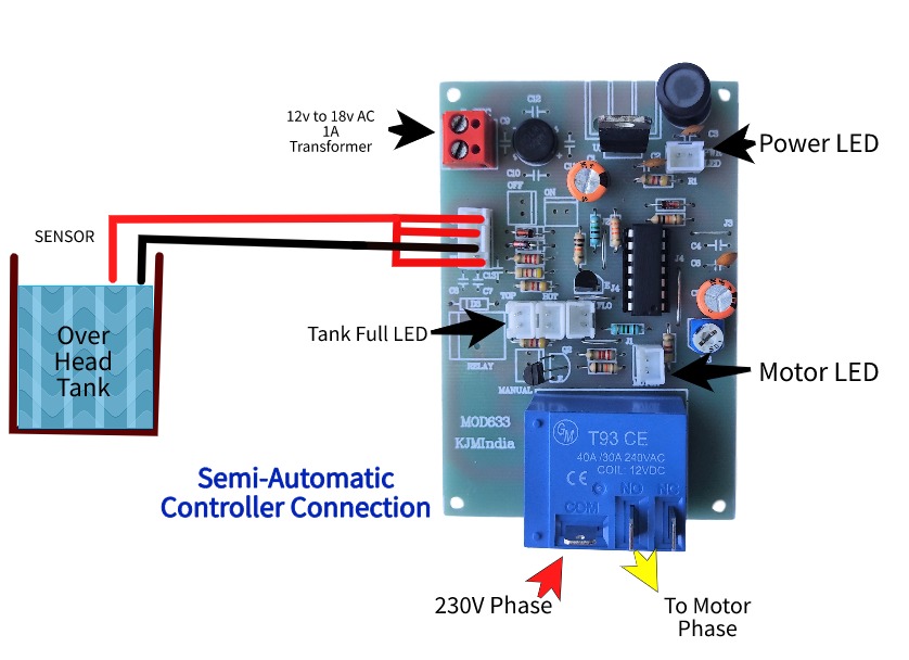
Semi-automatic Controller Connection Diagram
Same board can be used as a semi-automatic water level controller with or without dry run protection feature. In this case, we can use only the SS metal sensors instead of a float switch.
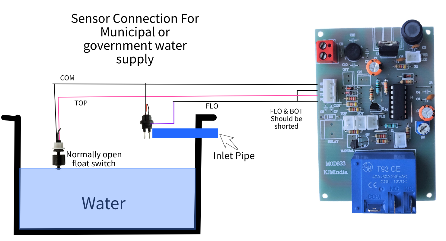
Sensor Connection For Municipal or Government Water Supply
Can use any of the following Float Switches
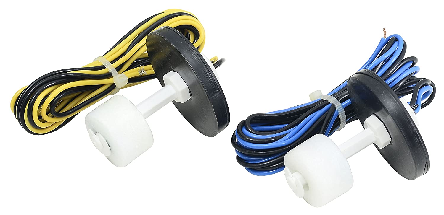
Horizontal Magnetic Float Switch(Normally Open)
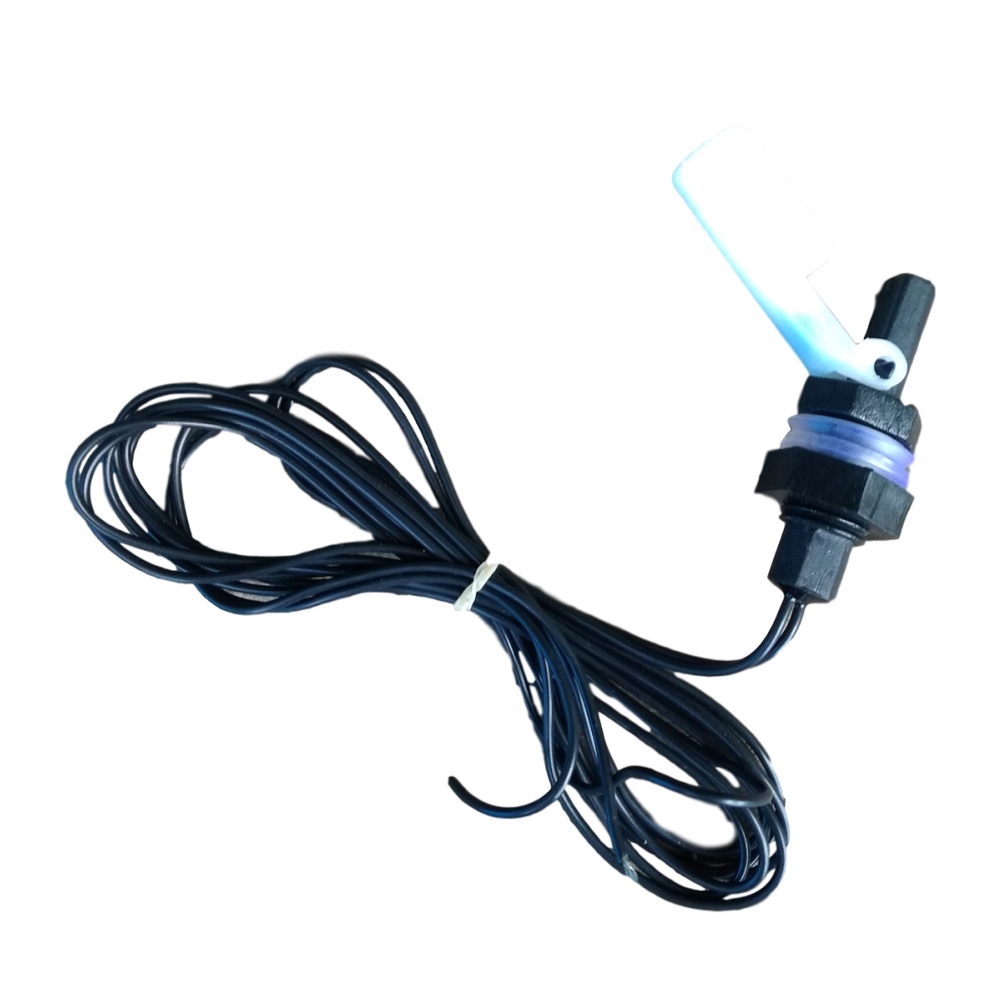
Vertical Magnetic Float Switch (Normally Open)
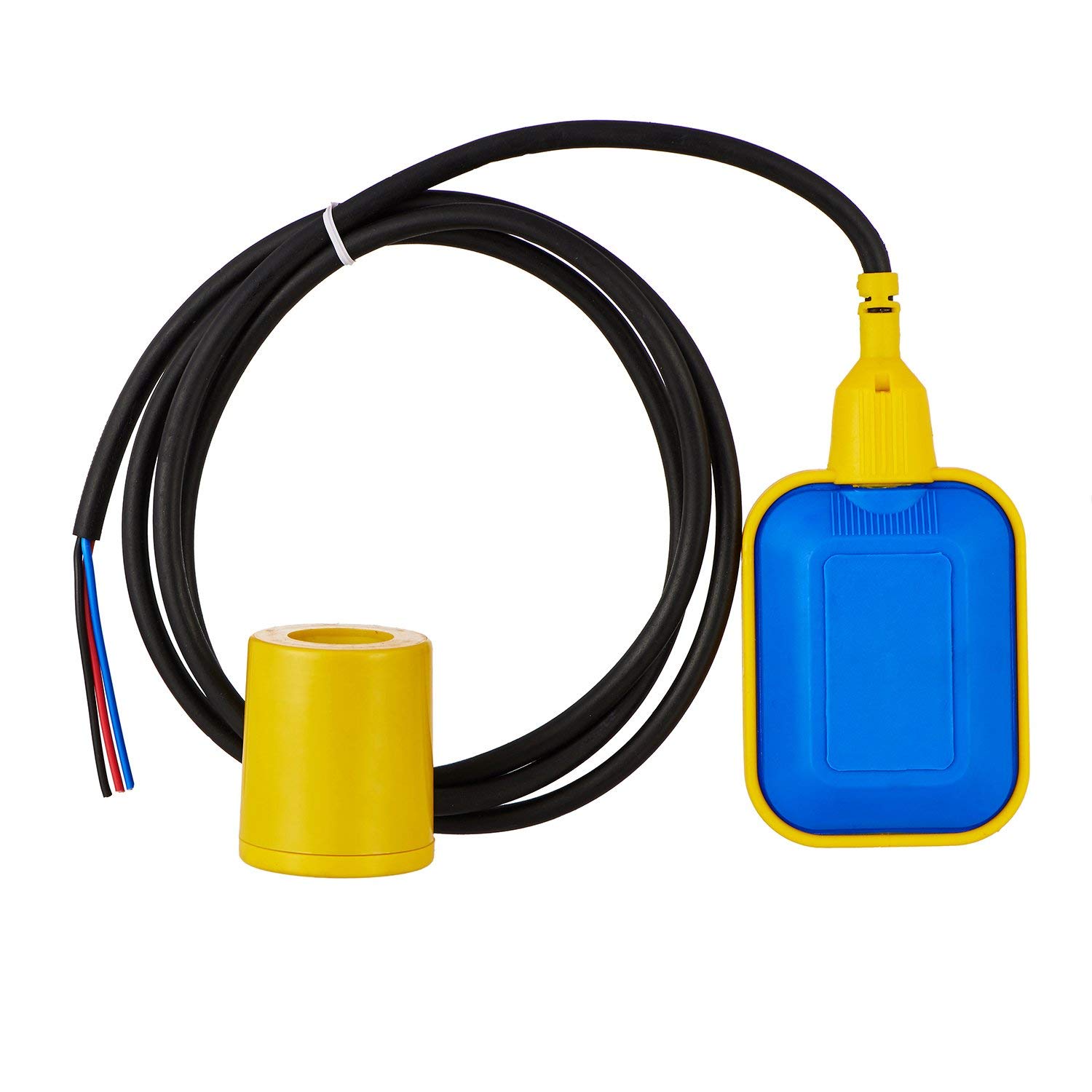
Cable Float Switch 5A, 230V
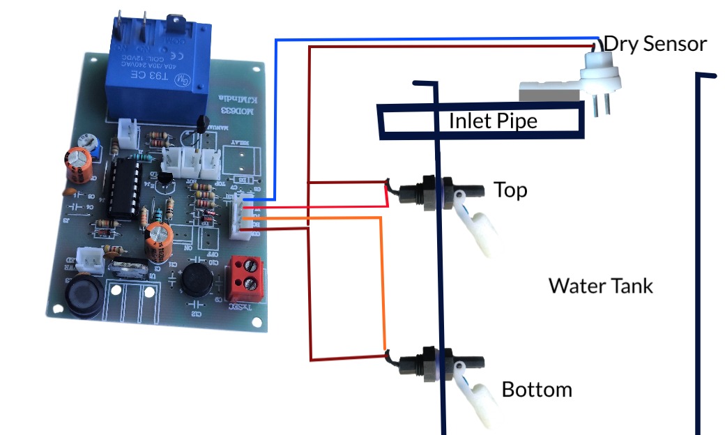
Top and Bottom sensors are shorted. One terminal of float switch is connected to the shorted terminal and black wire of the float is connected to the common. (If you have any doubt, please comment below your queries). Though it is a 230v cable float, here we are going to use only 12 volts.
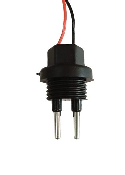
Dry Run Sensor
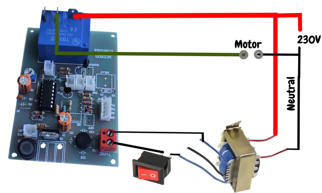
Water Level Controller Power And Relay Connection Diagram
Water Level Controller Sensor Connection Diagram
Working Video
✅ Advantages
- Prevents motor burnouts with dry run protection 🚱
- Saves electricity & water ⚡💧
- Ensures reliable water supply for daily use
- Easy to build with commonly available parts 🛠️
- Can be upgraded for semi-automatic or full-automatic operation
🔚 Conclusion
The Water Level Controller Circuit with Motor Dry Run Protection is a must-have solution for anyone looking to manage water tanks efficiently. It not only automates the water filling process but also protects your mono-block pump from costly damages. With its low cost, reliability, and easy availability of parts, this project is ideal for DIY enthusiasts, students, and homeowners alike. 🏠⚡
You should also read:
Semi-Automatic Water Level Controller Circuit Using 555 Timer
Managing water efficiently is crucial to avoid wastage and overflow 🚰. A semi-automatic water level controller circuit using a 555 timer IC provides a simple yet effective solution for controlling water pumps. This project not only prevents tank overflow but also reduces manual effort. By using a 555…
Continue reading...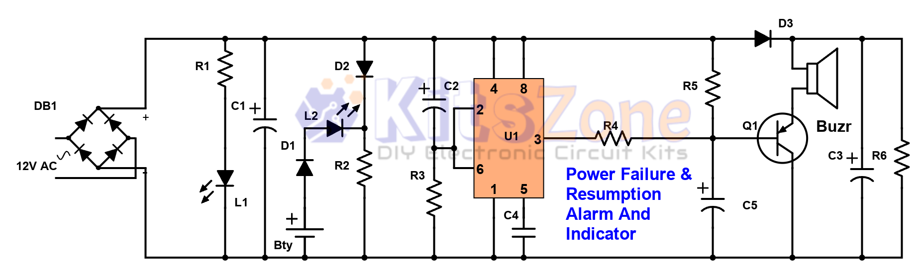
Power Failure and Resumption Alarm Circuit using 555 IC
⚡ Power cuts can cause inconvenience, equipment damage, and even safety risks. That’s why a Power Failure and Resumption Alarm Circuit using 555 Timer IC is a simple yet powerful solution! This DIY electronics project not only alerts you when electricity goes off but also notifies you…
Continue reading...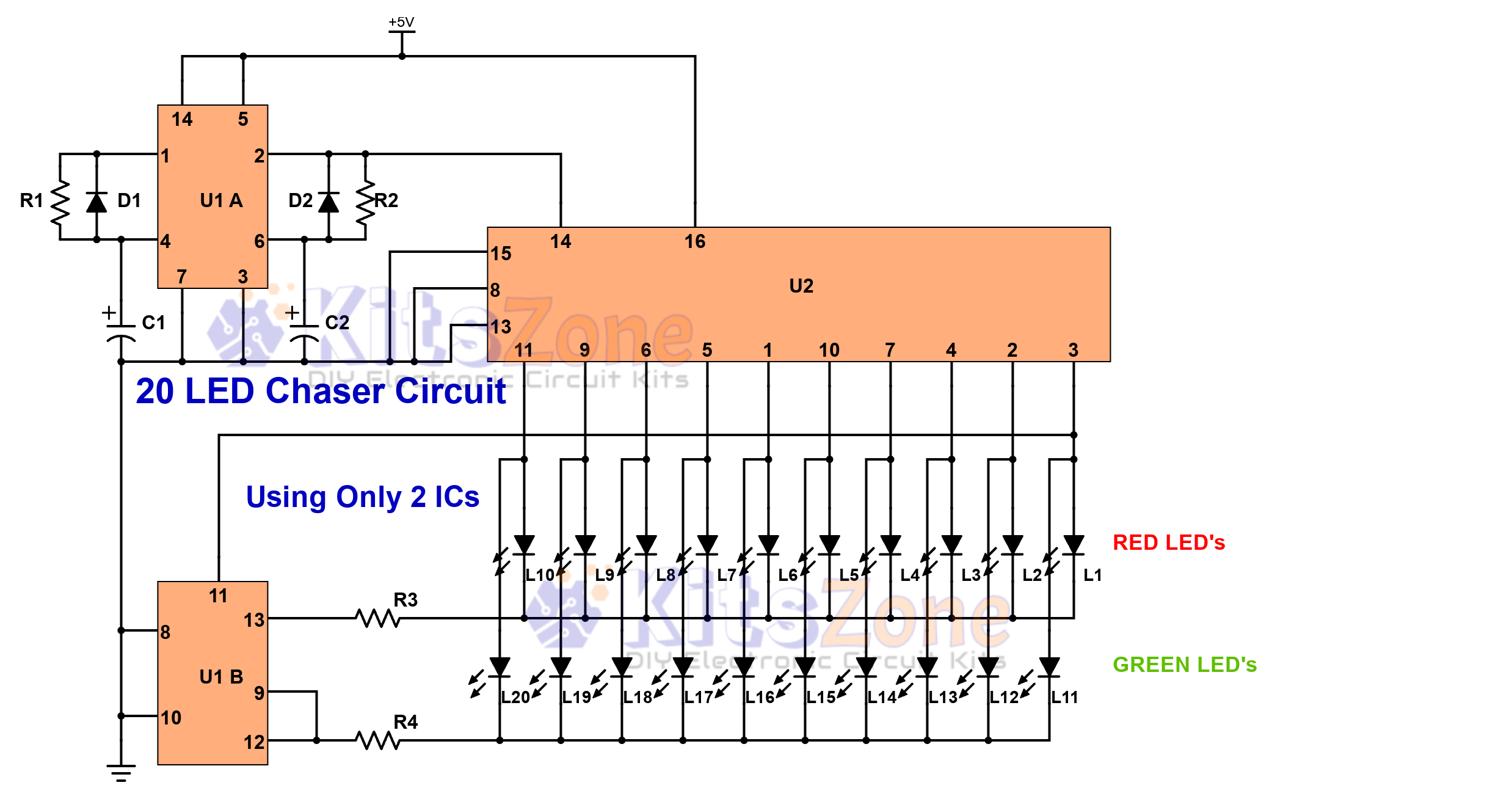
Light Chaser Circuit Using Cd4017 And Cd4013
Looking for a fun and easy electronics project? 🤔 A 20 LED chaser circuit Using Cd4017 And Cd4013 is a perfect DIY project for beginners and hobbyists. Instead of the commonly used 555 timer, this project uses CD4017 (decade counter IC) and CD4013 (dual flip-flop IC) to create a smooth light…
Continue reading...