
Water Level Controller Circuit Using Cable Float Switch
A water level controller circuit using a cable float switch is an effective way to automatically manage water in tanks without human effort. It not only prevents water wastage but also saves electricity, time, and protects the motor pump from dry runs. ✅ Whether in homes, apartments, or industries, this circuit ensures a reliable water supply system.
In this post, we’ll discuss a simple and low-cost water level controller using float switches and a transistor. This circuit is suitable for overhead tanks (OHT) and sumps, and can even be used with other non-heated liquids like oil. 🛢️

How the Water Level Controller Works ⚙️🔋
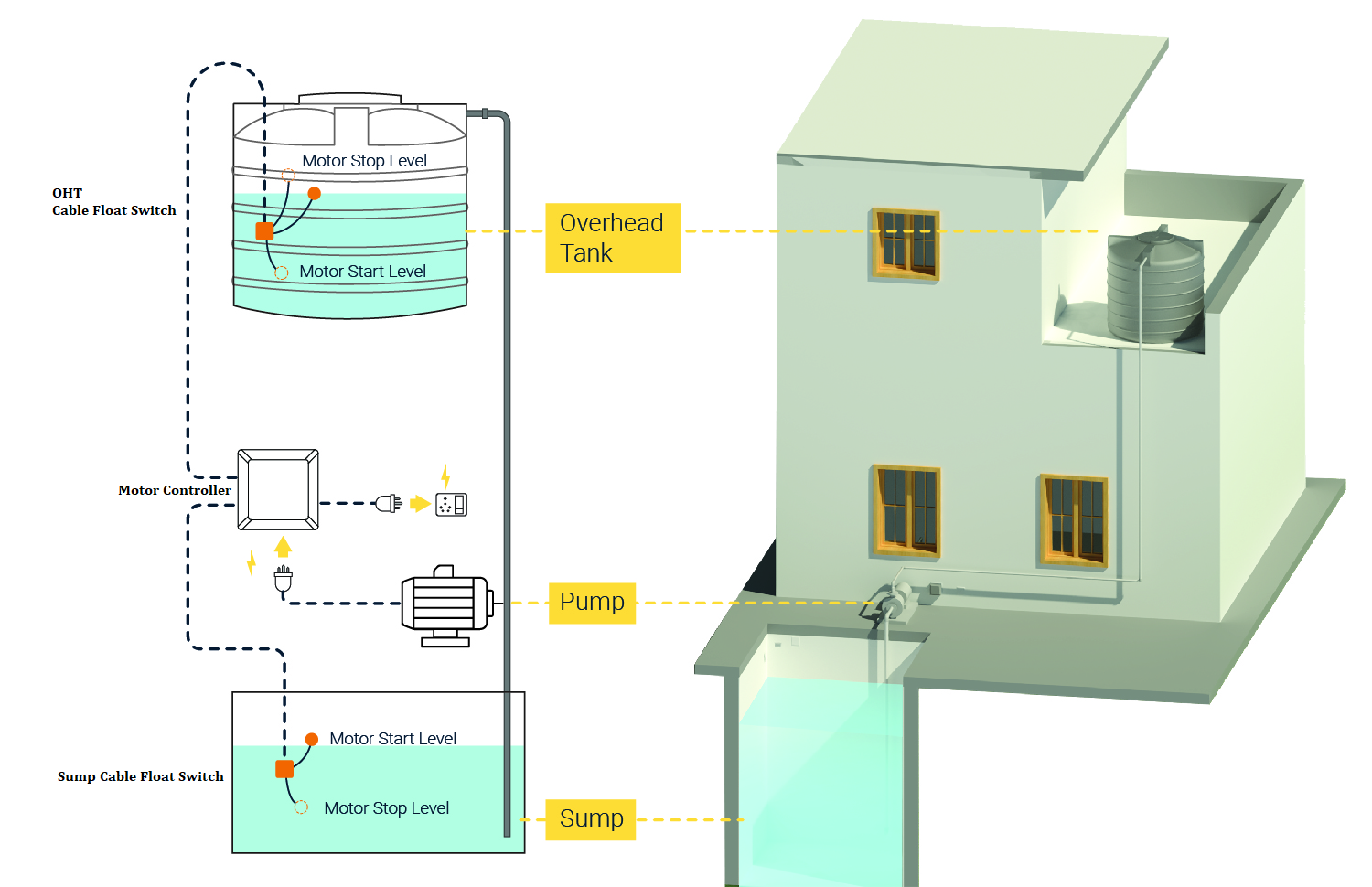
This water level controller uses a single NPN transistor (2N2222) along with two cable float switches to monitor sump and tank levels. The circuit ensures that:
- The motor pump runs only when water is available in the sump.
- It stops automatically when the overhead tank is full.
- It protects the motor from dry running.
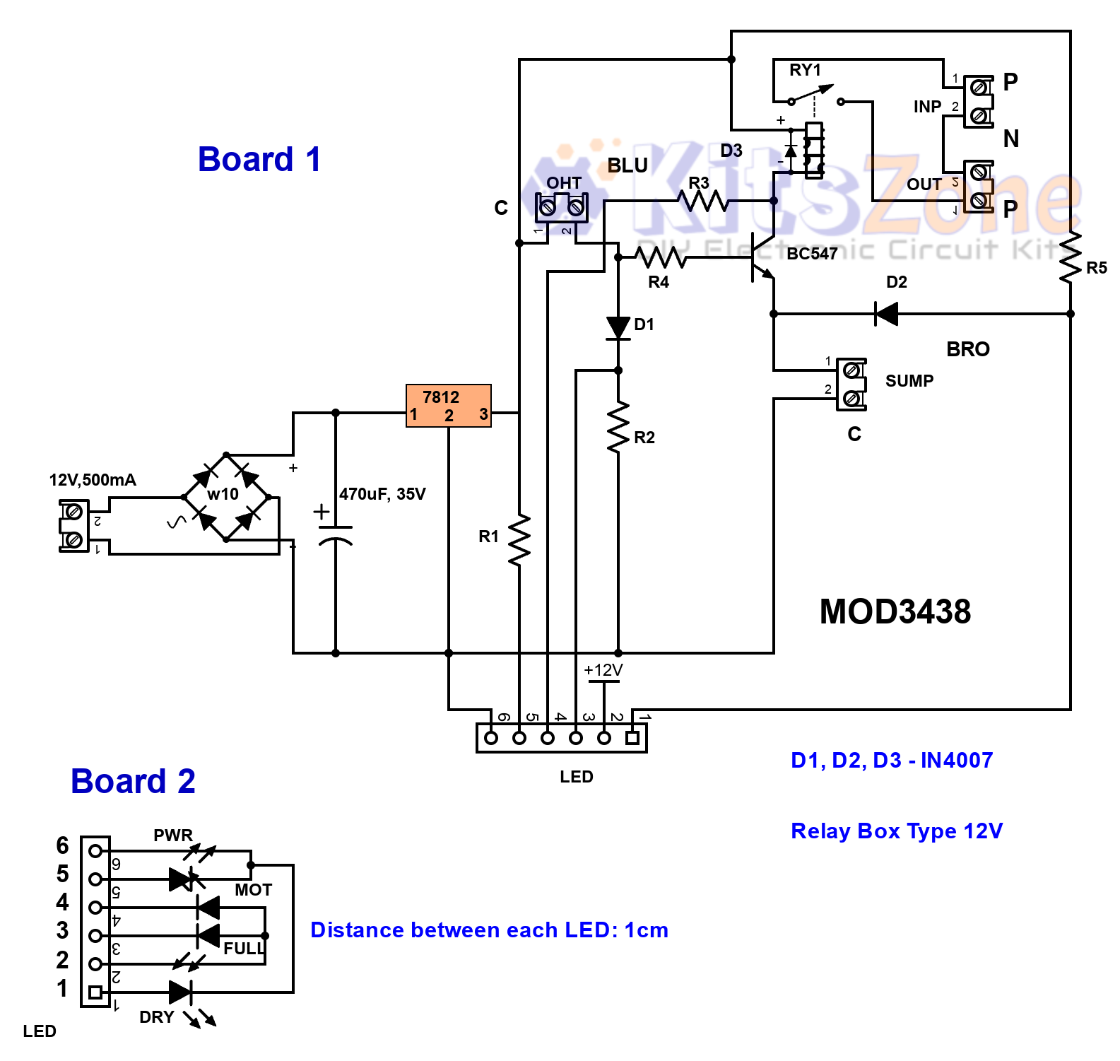
A 7812 voltage regulator IC provides a stable supply, while a 40A relay controls the motor. Choosing good-quality float switches is essential for reliable performance.
👉 Float switches generally have three wires:
- C (Black)
- BLU (Blue)
- BRO (Brown)
For this project:
- Overhead tank uses Black + Blue wires.
- Sump uses Black + Brown wires.
Circuit Operation Scenarios 🔄
1️⃣ Both sump & tank empty
- Power LED ON
- Yellow LED ON
2️⃣ Sump full, tank empty
- Power LED ON
- Motor ON LED ON
3️⃣ Both sump & tank full
- Power LED ON
- Full Tank LED ON
4️⃣ Tank full, sump empty
- Power LED ON
- Full Tank LED ON
- Sump Dry LED ON
Parts Required 🧰🔧
- Transformer: 12V, 500mA or a high quality 12v SMPS module
- Bridge Rectifier: W10 (DB1)
- Capacitor: 470µF, 50V (C1)
- Voltage Regulator IC: 7812 (U1)
- Resistors: R1, R2, R3, R5 = 4.7KΩ, R4 = 3.3KΩ
- Diodes: D1, D2, D3 = IN4007
- Transistor: 2N2222 (Q1)
- Relay: 12V, 30A (RY1)
- Terminal Blocks: Power, OHT, Sump, INP (optional), OUT (optional)
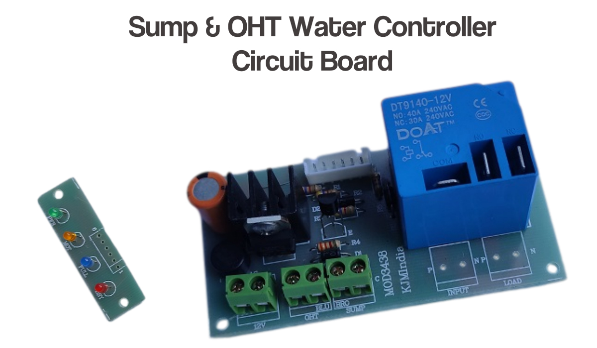
- LED Indicators: Power, Motor ON, Tank Full, Sump Dry
💡 Tip: Assemble on a general-purpose PCB to keep costs low if you’re building for personal use.
Role of BJT used in this circuit
- Universality: The board will work with both low-current sensors and mechanical floats.
- Contact wear / arcing: DC switching tends to produce more arcing than AC at small voltages — a transistor can reduce arcing across a fragile sensor contact by taking the switching current off the contact. For a proper mechanical float rated for the coil current this is minor, but it can matter for cheap/dirty contacts or repeated cycles.
- Noise / long cable runs: Long float cables pick up EMI; a transistor placed on the board can help produce a clean switching action and keep noisy currents off sensor wiring.
- Logic / indicator integration: The transistor lets the designer use the same sensing node to drive LEDs, thresholds, or logic without loading the float contact.
- Safety margin: If someone later replaces the float with a low-current detector, the board still works.
Advantages of Using This Water Level Controller 🌟
- ✅ Saves water by preventing overflow.
- ✅ Protects motor from dry run damage.
- ✅ Reduces electricity consumption.
- ✅ Low-cost and DIY friendly.
- ✅ Suitable for homes, apartments, and small industries.
Connection Details
You should also read:
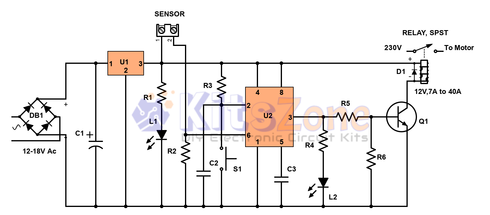
Semi-Automatic Water Level Controller Circuit Using 555 Timer
Managing water efficiently is crucial to avoid wastage and overflow 🚰. A semi-automatic water level controller circuit using a 555 timer IC provides a simple yet effective solution for controlling water pumps. This project not only prevents tank overflow but also reduces manual effort. By using a 555…
Continue reading...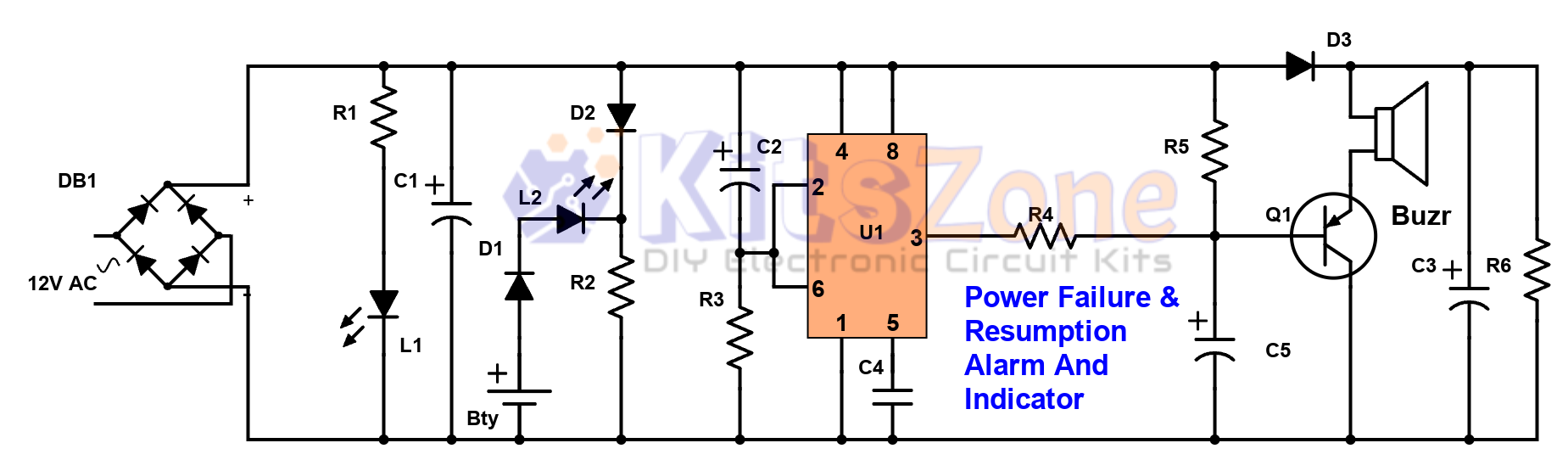
Power Failure and Resumption Alarm Circuit using 555 IC
⚡ Power cuts can cause inconvenience, equipment damage, and even safety risks. That’s why a Power Failure and Resumption Alarm Circuit using 555 Timer IC is a simple yet powerful solution! This DIY electronics project not only alerts you when electricity goes off but also notifies you…
Continue reading...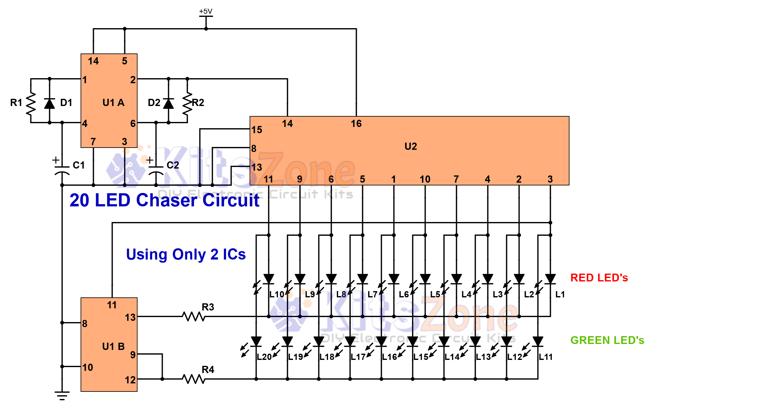
Light Chaser Circuit Using Cd4017 And Cd4013
Looking for a fun and easy electronics project? 🤔 A 20 LED chaser circuit Using Cd4017 And Cd4013 is a perfect DIY project for beginners and hobbyists. Instead of the commonly used 555 timer, this project uses CD4017 (decade counter IC) and CD4013 (dual flip-flop IC) to create a smooth light…
Continue reading...