
Semi-Automatic Water Level Controller Circuit Using 555 Timer

Managing water efficiently is crucial to avoid wastage and overflow 🚰. A semi-automatic water level controller circuit using a 555 timer IC provides a simple yet effective solution for controlling water pumps. This project not only prevents tank overflow but also reduces manual effort. By using a 555 timer, relay, transistor, and sensors, this circuit ensures automatic pump cut-off once the water tank is full ✅.
If you are looking for a DIY water level controller project, this is one of the most reliable and beginner-friendly electronics circuits you can build at home 🏠.
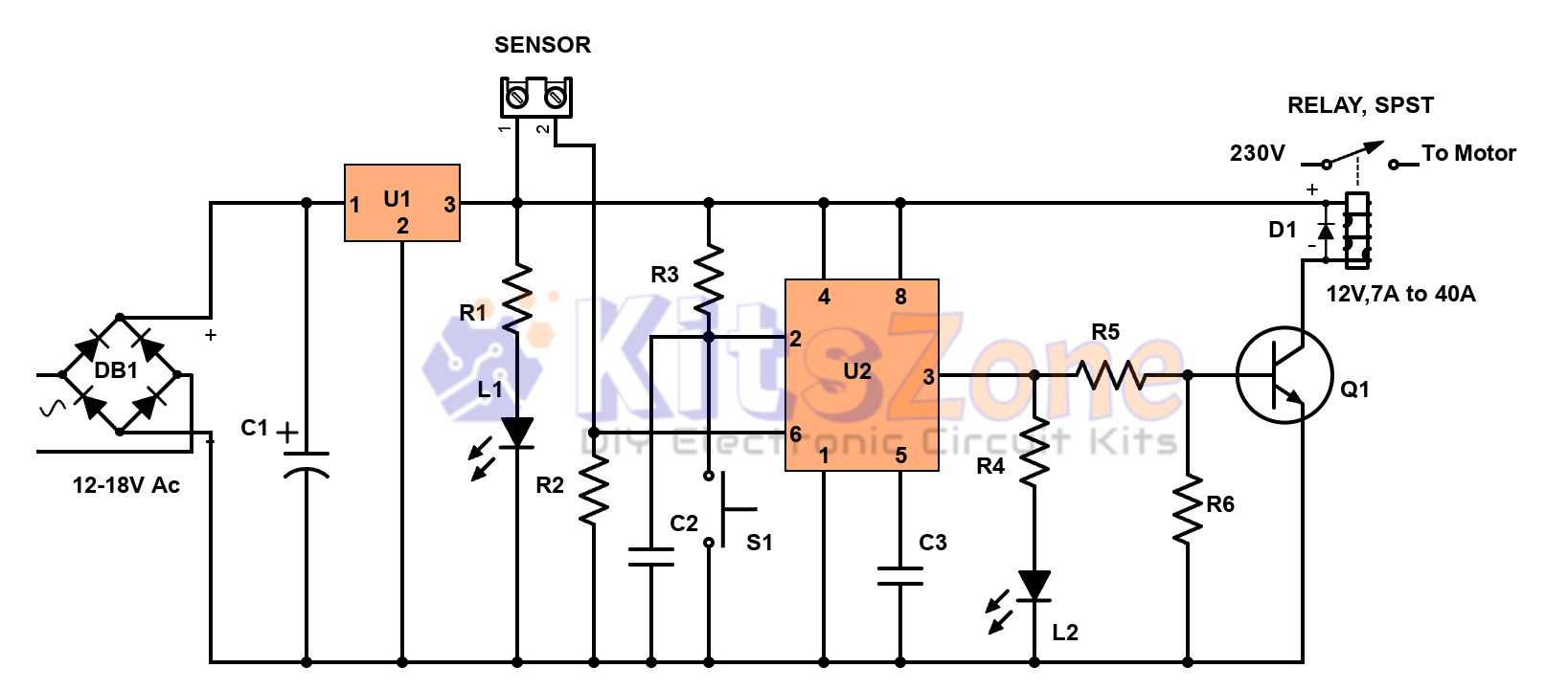
Circuit Diagram
How the Semi-Automatic Water Level Controller Works ⚙️
This water level controller circuit is designed to control the pump motor and avoid overflow:
- The sensor detects water level in the tank and sends a signal to the 555 timer IC.
- The 555 timer (in bistable mode) processes the signal.
- A transistor driver controls the relay, which switches the motor ON/OFF.
- LED indicators show the pump status 🔴🟢.
👉 It is called semi-automatic because you must press the switch to start the motor, but it turns OFF automatically when the tank is full.
You can replace contact-type sensors with magnetic float switches for better durability.
Parts Required 🛠️
Here’s the list of parts you’ll need to build this project:
- Power Supply: 12v smps module or transformer, DB107 bridge rectifier, IC 7810/7812
- Main IC: NE555 Timer IC
- Resistors: 4.7K, 100K, 10K, 2.2K, 47K
- Capacitors: 100uF/25V, 0.001uF, 0.01uF
- Diode: 1N4007
- Transistor: 2N2222
- Relay: 12V (higher amp rating for higher HP motors)
- LEDs: Red (Power), Green (Motor Running)
- Switch: Momentary (Normally Open)
Working Principle 🔌
- Start Motor → Press the switch (S1) to trigger pin 2 of the 555 timer.
- Pump Running → Output drives the transistor, energizing the relay, and motor starts.
- Tank Full → Sensor at the top detects water and cuts off the motor automatically.
- Indicators → Red LED shows power, Green LED indicates motor ON.
This makes the system reliable, efficient, and safe for household use.
Benefits of Semi-Automatic Water Level Controller ✅
- 🚫 Prevents tank overflow and water wastage
- 🏠 Easy to build and install at home
- 🔋 Low-cost solution with minimal components
- ⚡ Can handle higher power pumps with bigger relays
- 💡 LED indicators for user-friendly operation
Conclusion 🎯
The semi-automatic water level controller using 555 timer IC is a smart DIY electronics project for beginners and hobbyists. It ensures automatic pump cut-off when the tank is full, saving water and electricity. By using simple components like the 555 timer, relay, and sensors, you can create a reliable water management system at home.
⚠️ Note: This circuit is ideal for project and educational purposes only. For commercial or long-term use, the design must be modified and upgraded for better safety and durability.
💡 Whether you are an electronics enthusiast or someone looking for a practical home automation project, this circuit is worth trying!
You should also read:
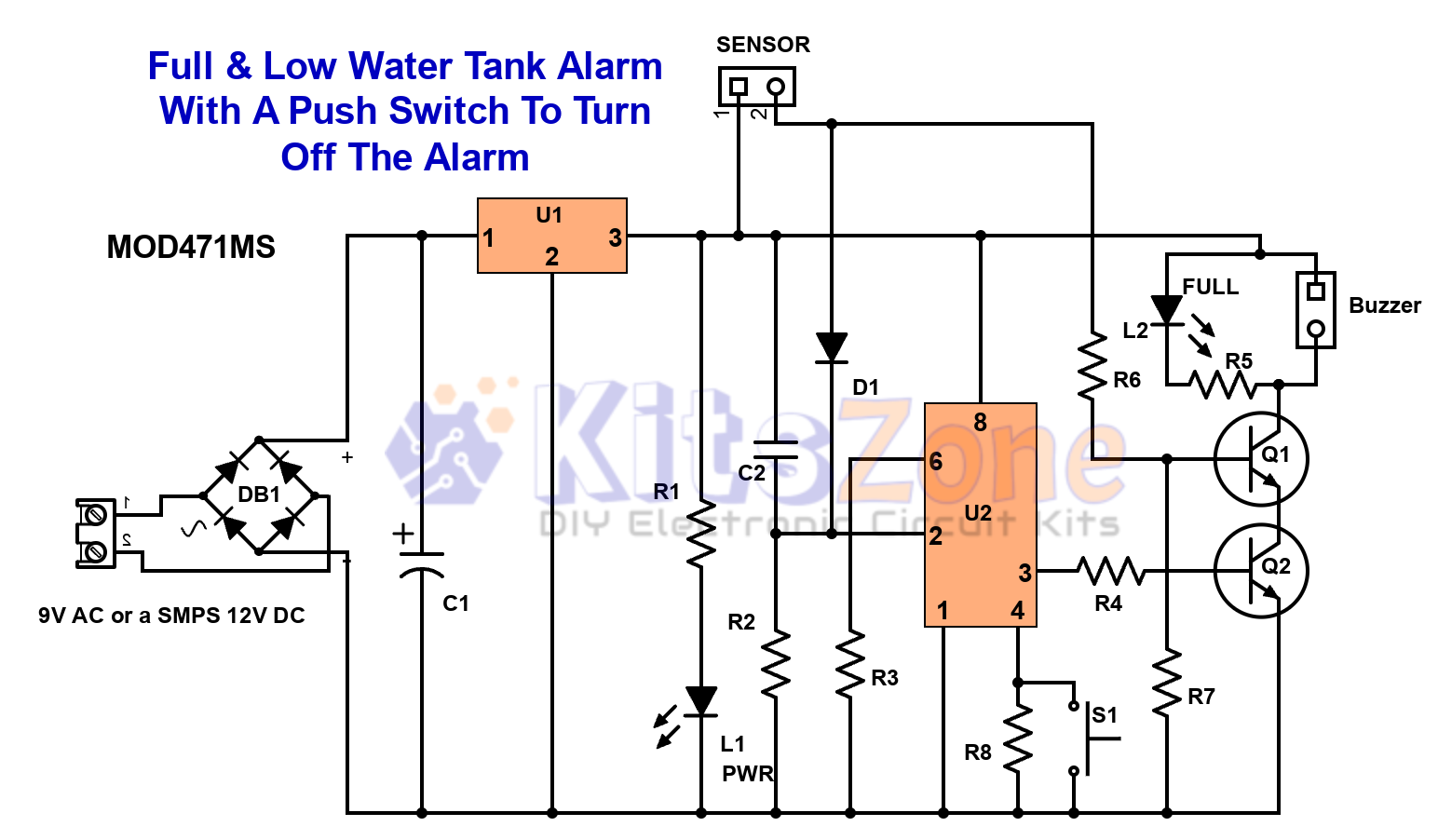
Full & Low Water Tank Alarm Circuit Using 555 Timer Ic
💧 Are you tired of water overflowing from your overhead tank or running out of water at the wrong time? A Full & Low Water Tank Alarm Circuit using 555 Timer IC is the perfect DIY solution to ensure efficient water management. This smart circuit not only…
Continue reading...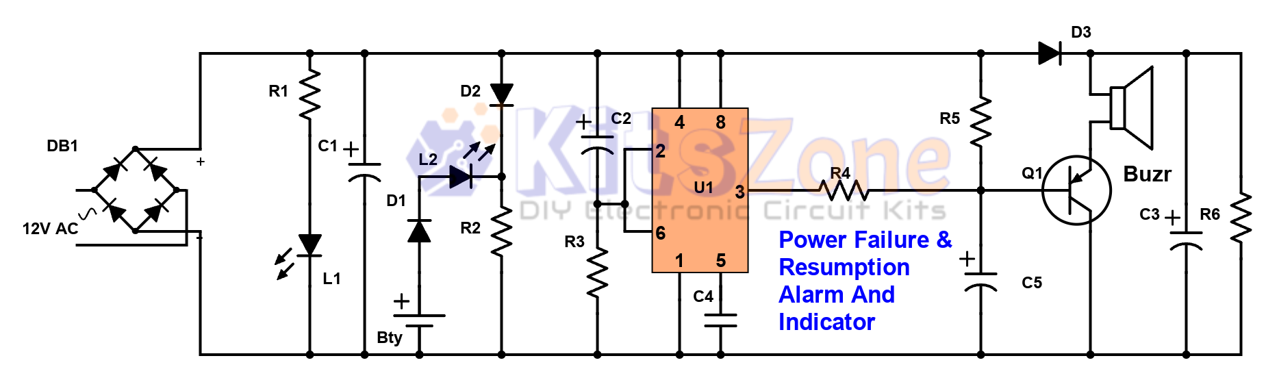
Power Failure and Resumption Alarm Circuit using 555 IC
⚡ Power cuts can cause inconvenience, equipment damage, and even safety risks. That’s why a Power Failure and Resumption Alarm Circuit using 555 Timer IC is a simple yet powerful solution! This DIY electronics project not only alerts you when electricity goes off but also notifies you…
Continue reading...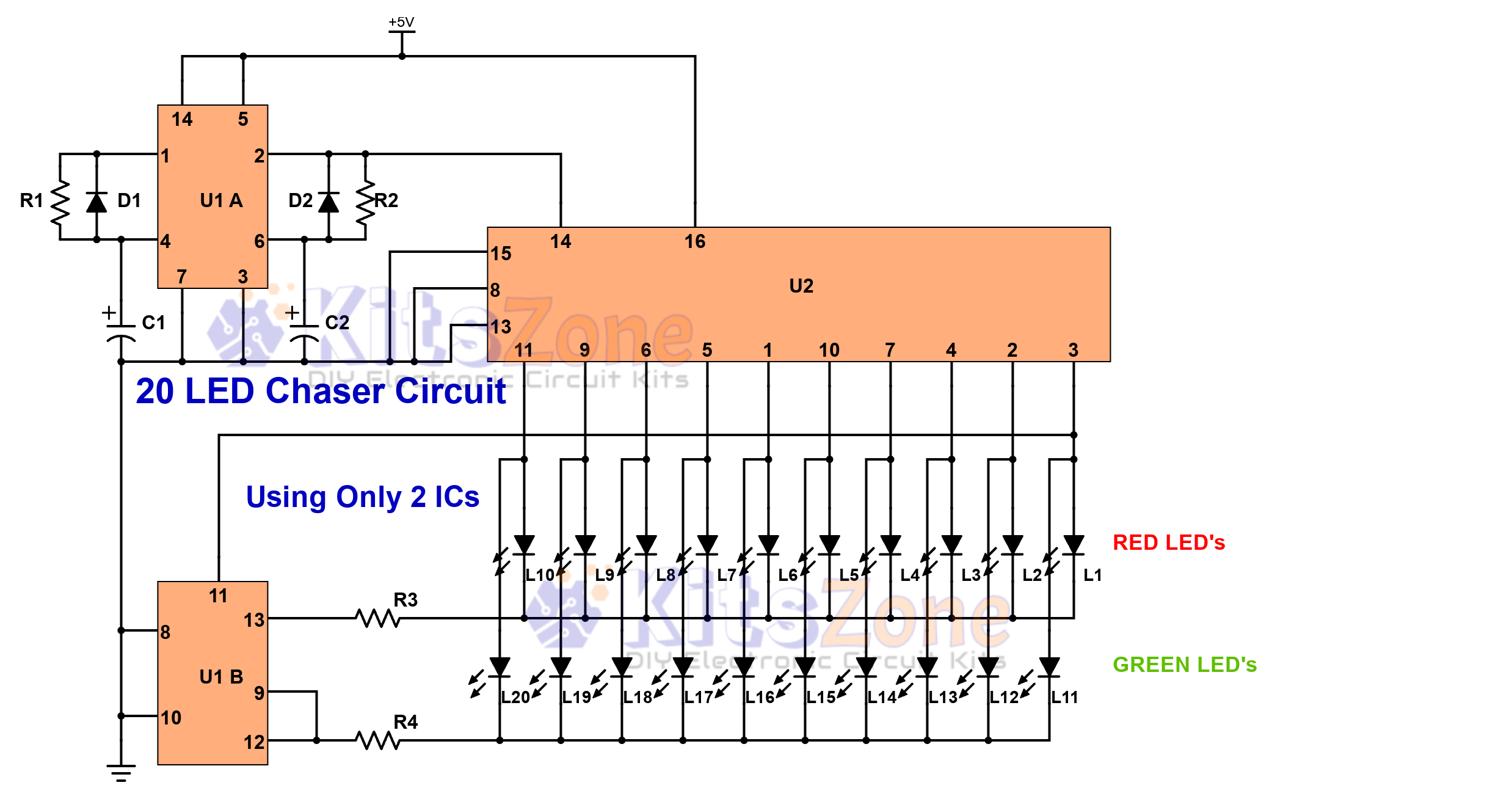
Light Chaser Circuit Using Cd4017 And Cd4013
Looking for a fun and easy electronics project? 🤔 A 20 LED chaser circuit Using Cd4017 And Cd4013 is a perfect DIY project for beginners and hobbyists. Instead of the commonly used 555 timer, this project uses CD4017 (decade counter IC) and CD4013 (dual flip-flop IC) to create a smooth light…
Continue reading...