
Power Failure and Resumption Alarm Circuit using 555 IC

⚡ Power cuts can cause inconvenience, equipment damage, and even safety risks. That’s why a Power Failure and Resumption Alarm Circuit using 555 Timer IC is a simple yet powerful solution! This DIY electronics project not only alerts you when electricity goes off but also notifies you when it returns. ✅ With just a few components, you can easily build this circuit at home and enjoy peace of mind during unexpected outages.
🌟 Benefits of Power Failure and Resumption Alarm
- 🖥️ Protects Equipment – Prevents damage to sensitive devices like computers, servers, and medical equipment.
- 🛡️ Ensures Safety – Alerts you when emergency lights, alarms, or security systems lose power.
- 💼 Business Continuity – Helps companies minimize downtime and resume operations quickly.
- 🔋 Energy Awareness – Provides insights into power interruptions for better energy management.
- 😌 Peace of Mind – Stay worry-free knowing outages and restorations are instantly detected.
⚙️ How the Circuit Works
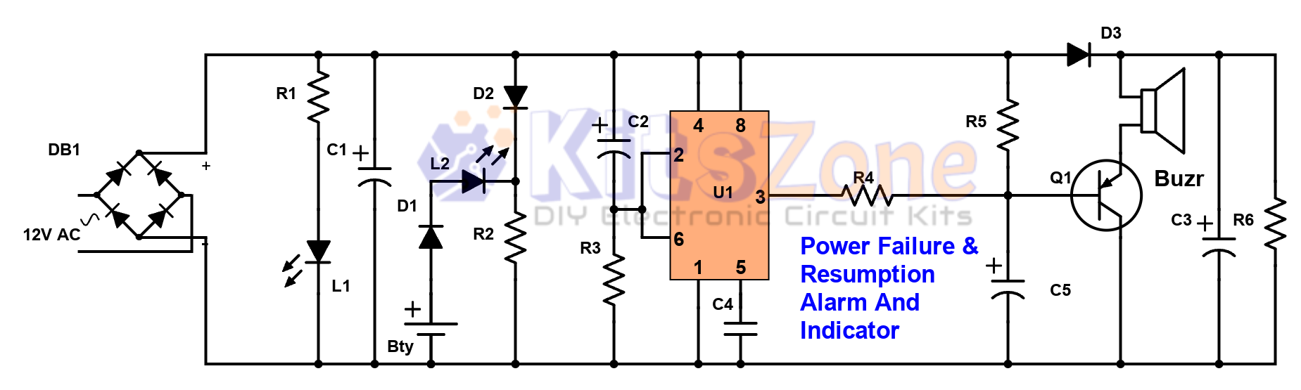
This circuit is designed to detect power failure and restoration in AC mains using a 555 timer IC in monostable mode.
- Power Failure:
- When mains fail, transistor Q1 (BC558) is triggered.
- Stored charge in capacitor C3 powers the buzzer and Red LED (L2).
- Increasing C3 (1000µF → 2200µF or 4500µF) increases alarm duration.
- Power Resumption:
- When mains return, Green LED (L1) lights up.
- A buzzer sounds for a short duration, determined by R3 and C2 values.
- Alarm automatically stops after the set time.
- The circuit runs on a 9V battery with a 12V power supply.
- It can also give short beeps for voltage fluctuations.
- Compact enough to be installed in homes, offices, shops, or industries.
🛠️ Components Required
Resistors (¼ W):
- R1 – 4.7K
- R2 – 3.3K
- R3 – 100K
- R4 – 2.2K
- R5 – 4.7K
- R6 – 10K (optional)
Capacitors:
- C1 – 47µF / 25V
- C2 – 100µF / 25V
- C3 – 1000µF / 25V
- C4 – 0.01µF ceramic
- C5 – 47µF / 25V
Other Components:
- LEDs – L1 (Green), L2 (Red)
- Diodes – D1, D2, D3 (1N4007)
- DB1 – DB107 Bridge Rectifier
- IC – 555 Timer
- Q1 – BC558 (PNP transistor)
- 9V Battery
- DC Buzzer
- 0–12V, 200mA Transformer
- General-purpose PCB
✅ Final Thoughts
The Power Failure and Resumption Alarm Circuit using 555 Timer IC is an excellent DIY project for anyone who wants to stay informed about power status. ⚡ Whether for home, office, or industry, this circuit ensures safety, protects equipment, and provides timely alerts. With a handful of components, you can easily build it and enjoy uninterrupted confidence during outages! 🔋🔔
Version2: With Manual off For Failure Alarm
You should also read:
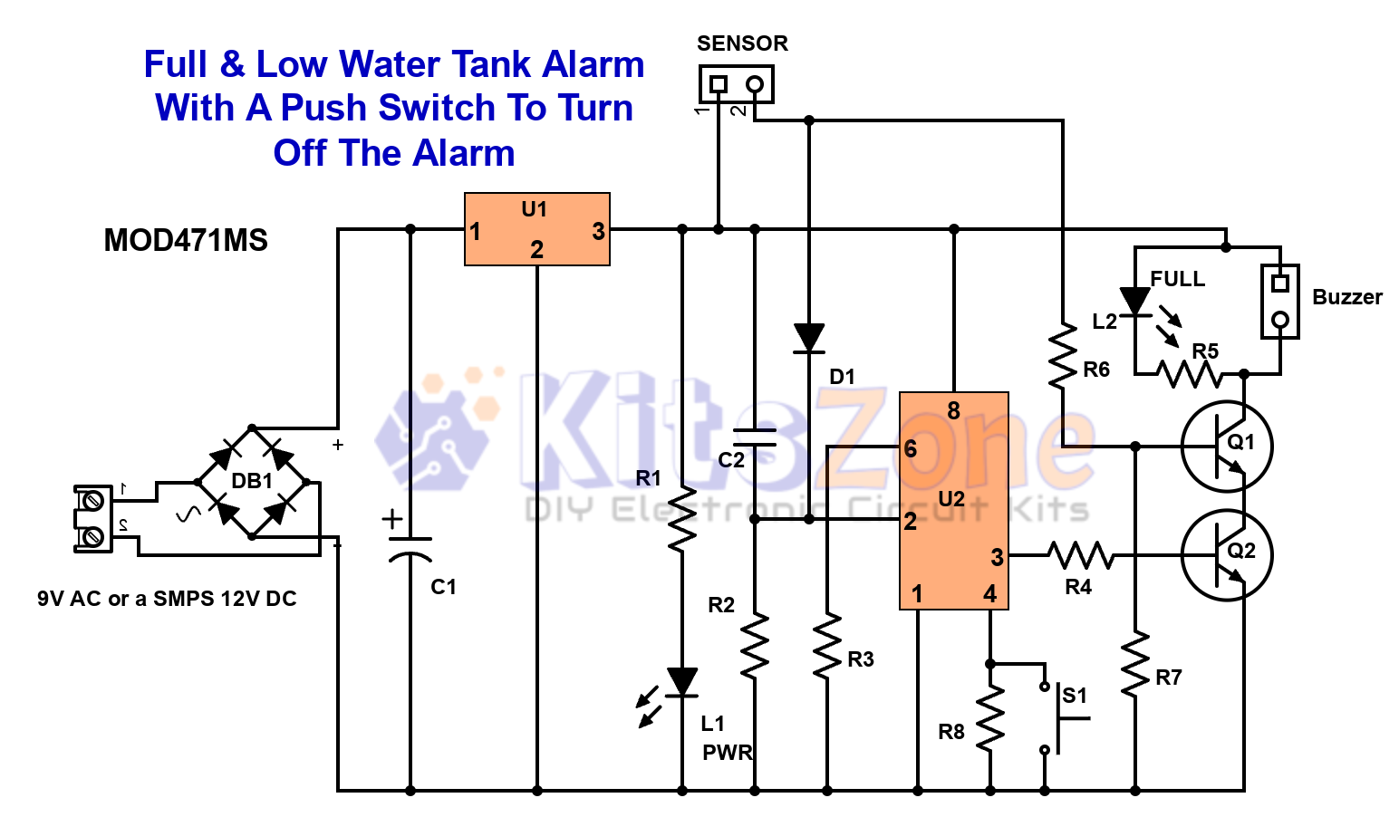
Full & Low Water Tank Alarm Circuit Using 555 Timer Ic
💧 Are you tired of water overflowing from your overhead tank or running out of water at the wrong time? A Full & Low Water Tank Alarm Circuit using 555 Timer IC is the perfect DIY solution to ensure efficient water management. This smart circuit not only…
Continue reading...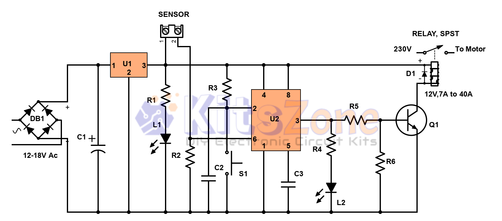
Semi-Automatic Water Level Controller Circuit Using 555 Timer
Managing water efficiently is crucial to avoid wastage and overflow 🚰. A semi-automatic water level controller circuit using a 555 timer IC provides a simple yet effective solution for controlling water pumps. This project not only prevents tank overflow but also reduces manual effort. By using a 555…
Continue reading...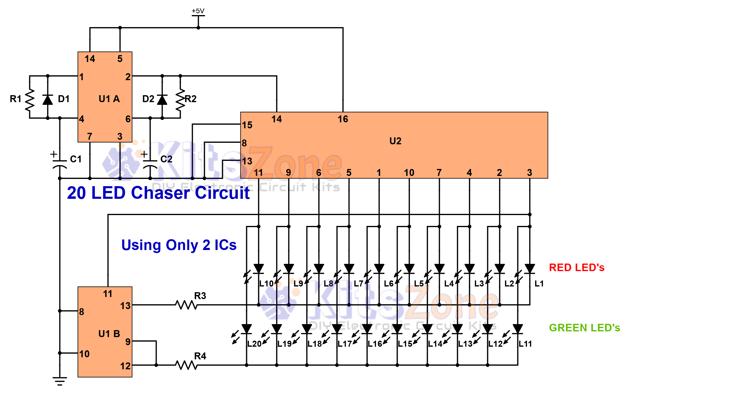
Light Chaser Circuit Using Cd4017 And Cd4013
Looking for a fun and easy electronics project? 🤔 A 20 LED chaser circuit Using Cd4017 And Cd4013 is a perfect DIY project for beginners and hobbyists. Instead of the commonly used 555 timer, this project uses CD4017 (decade counter IC) and CD4013 (dual flip-flop IC) to create a smooth light…
Continue reading...