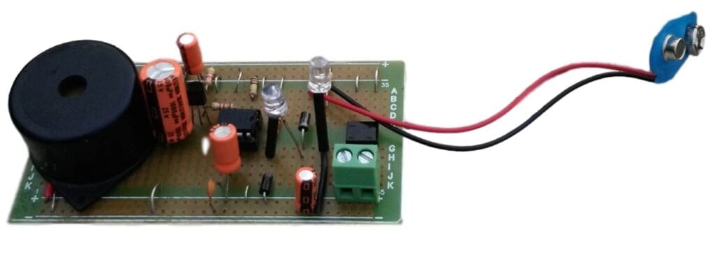
Power failure and resumption alarm and indicator circuit using 555 timer ic
This is a very simple circuit built using only a few components to detect ac mains power failure and its resumption. The heart of the circuit is the most popular timer Ic 555 which is wired as monostable multivibrator.
Circuit Diagram

Parts Used
Resistors (All 1/4W)
- R1 – 4.7K
- R2 – 3.3K
- R3 – 100K
- R4 – 2.2K
- R5 – 4.7K
- R6 – 10K (optional)
Capacitors
- C1 – 47uF, 25V
- C2 – 100uF, 25V
- C3 – 1000uF, 25V
- C4 – 0.01uF ceramic
- C5 – 47uF, 25V
Led (3mm or 5mm)
- L1 – Green
- L2 – Red
Diode
- D1, D2, D3 – In4007
- DB1 – DB107 Bridge rectifier
Ic
- U1 – 555
Transistor
- Q1 – BC558 (PNP)
9V Battery, Dc Buzzer, 0-12V,200mA Transformer, general purpose pcb, etc.
Working
Battery, Diode D1, D2, Led L2 and resistor R2 are wired in such a way that the led L2 lights up only when power fails. When the power fails, the transistor Q1 is activated and is powered by the charge stored in the capacitor C3. Increasing the value of C3 from 1000uf to 2200 or 4500uF, increases the duration of the alarm during power failure.
Once the power resumes, green led L1 lights up and sounds an alarm for a time determined by R3 and C2. Increase or decrease the value of R3 and C2 as per your requirement. During power failure and resumption, the alarm sounds only for a certain time and switches off automatically.
The circuit works off a 9V battery and a 12v power supply. Apart from indicating the power failure and resumption, it sounds a short beep to indicate the voltage fluctuations. It can be housed in a box and installed where you want to monitor the status of mains.
Prototype

![[Multi-Colour] Automatic Night Lamp Circuit Diagram Using LDR And CD4017 | Kitszone.com](https://kitszone.com/wp-content/uploads/2024/11/Automatic-multicolour-night-light-circuit-390x220.jpg)


