Semi-Automatic Water Level Controller Circuit Project Using 555 Timer With Indicator
Mini Electronics Project
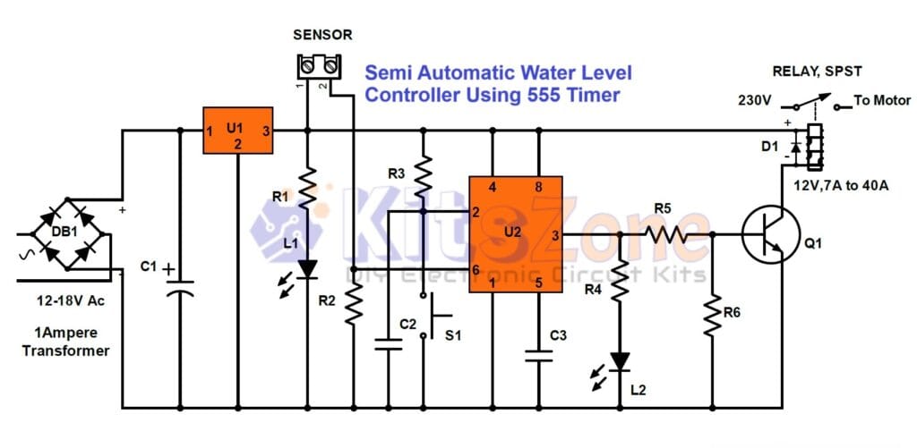
A semi-automatic water level controller circuit is used for automatically controlling the level of water in a tank and avoid overflowing. This circuit is made up of a sensor, timer chip, relay, pump driver and power supply. The sensor senses the water level in the tank and converts it to voltage. The timer chip takes care of sensing voltage from sensor and turns ON/OFF pump driver accordingly.
This is a very simple water controller circuit built using the popular 555 timer IC. It is called as semi-automatic water level controller because we have to manually switch on the circuit and it will turn off the water pump automatically once the level of water touches the contact type sensor placed at the top of of the water tank. Instead of using contact type sensors, we can also use magnetic float switches.
Circuit Diagram
Parts Required
DB1 – Bridge rectifier DB107
IC
U1 – 7810 or 7812
U2 – NE555 Timer IC
Resistors: (All 1/4W)
R1 – 4.7K
R2 – 100K
R3 – 10K
R4 – 4.7K
R5 – 2.2K
R6 – 47K
Capacitor:
C1 – 100uF/ 25V
C2 – 0.001uF ceramic
C3 – 0.01uF ceramic
Diode D1 – In4007
Led
L1 – Red, L2 – Green
S1 – Momentary Switch (Normally Open)
Q1 – Transistor 2N2222
RY1 – 12V Relay, 7A to 40A
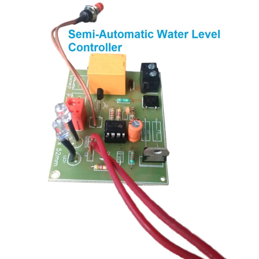
Circuit Board using 12V 7A Relay
Description
Led L1 is used to indicate the power whereas the Led L2 is used to indicate motor is running. 555 timer is wired in bistable mode. Motor is turned on by pressing the switch S1 momentarily that is connected to the pin 2 of the timer ic. We can also connect another momentary switch across the pin 6 and the positive rail of the circuit to turn off the motor if required. The output of the timer is fed to the base of the npn transistor to drive a 12V relay. We can use more ampere rating relay to drive high Hp motors.


