
Light Chaser Circuit Using Cd4017 And Cd4013
Looking for a fun and easy electronics project? 🤔 A 20 LED chaser circuit Using Cd4017 And Cd4013 is a perfect DIY project for beginners and hobbyists. Instead of the commonly used 555 timer, this project uses CD4017 (decade counter IC) and CD4013 (dual flip-flop IC) to create a smooth light chasing effect ✨.
This LED running light circuit is often seen in decoration lights, signboards, and even in some toys 🎉. By following this simple electronics circuit, you can easily build your own LED chaser at home with just a few components.

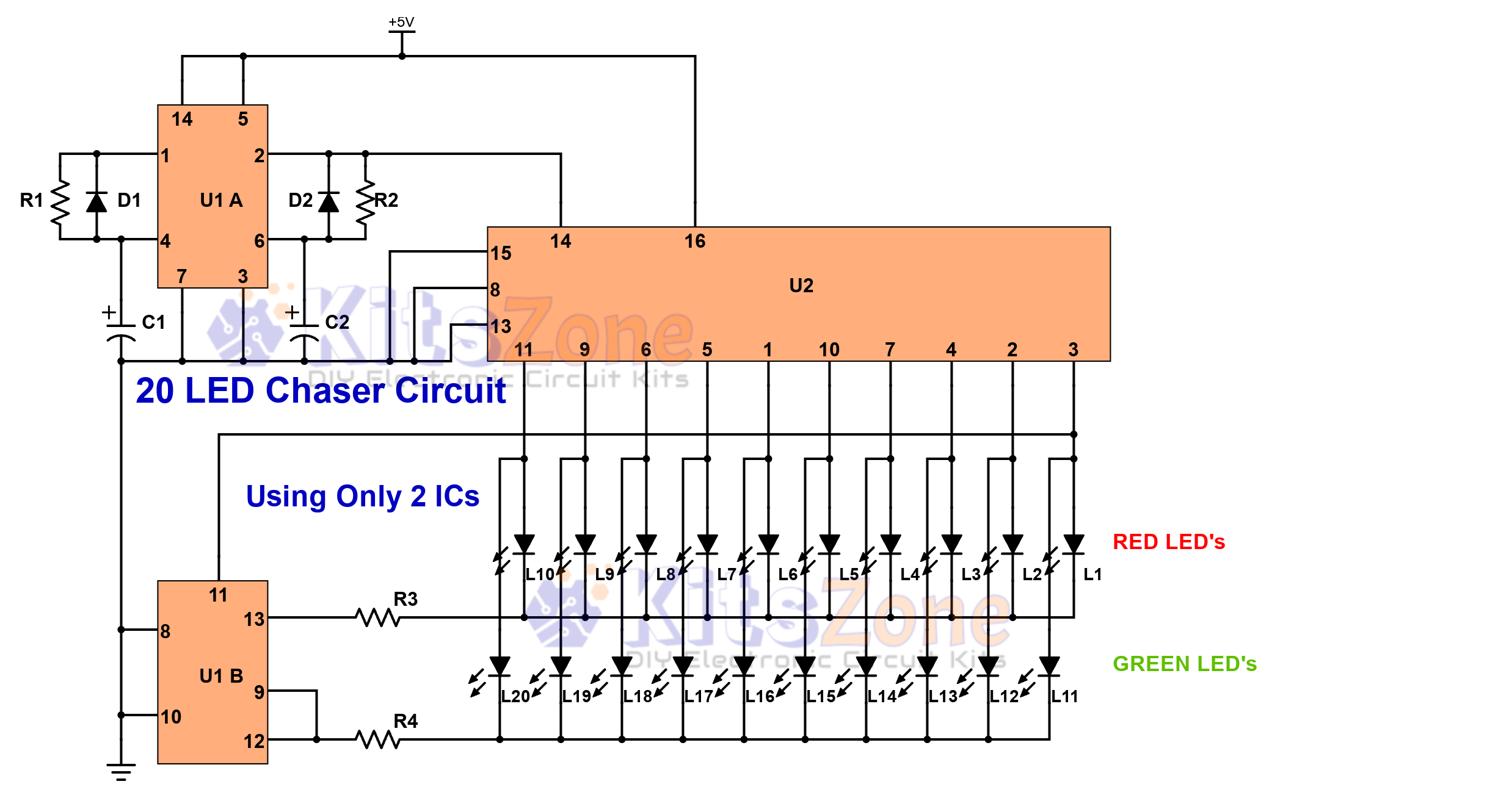
Working of 20 LED Chaser Circuit ⚡
- CD4017 👉 works as a divide-by-10 counter
- CD4013 👉 one flip-flop acts as a multivibrator (oscillator) & the other as a divide-by-2 counter
How it Works ⚡
- Output pin 2 of CD4013 connects directly to input pin 14 of CD4017.
- Pin 3 of CD4017 drives pin 11 of CD4013.
- The negative terminals of LEDs L1–L10 go to pin 13 of CD4017, while L11–L20 go to pin 12.
- As the cycle runs, the LEDs light up one after another and create a beautiful running effect 💡.
- The cycle keeps repeating as long as you keep the power on 🔋.
Parts Required 🛠️
Resistors (¼W):
- R1 & R2 = 6.8K Ω
- R3 & R4 = 4.7K Ω
Capacitors:
- C1 & C2 = 100µF (Use smaller values for faster chasing speed ⏩)
Diodes:
- D1 & D2 = 1N4148
ICs:
LEDs:
- L1–L20 (Any color of your choice 🌈)
Power Supply:
Others:
Breadboard or General Purpose PCB
Applications of LED Chaser Circuit 💡
- Decorative lighting for parties & festivals 🎇
- Advertising signboards ✨
- Learning project for electronics students 📚
- Toys and hobby circuits 🎮
You should also read:
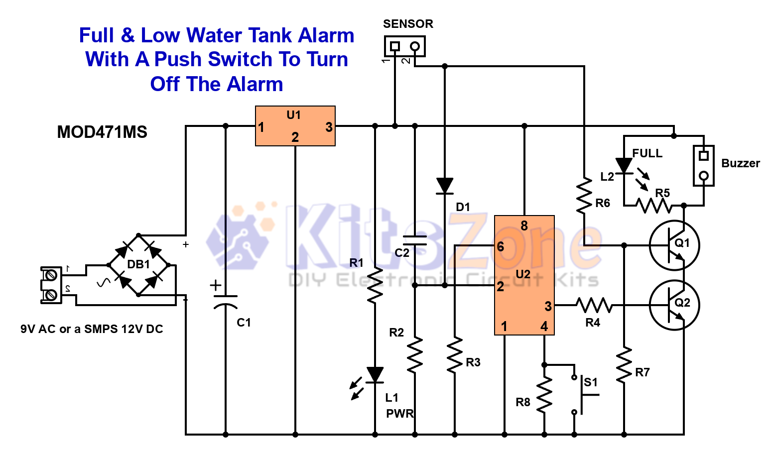
Full & Low Water Tank Alarm Circuit Using 555 Timer Ic
💧 Are you tired of water overflowing from your overhead tank or running out of water at the wrong time? A Full & Low Water Tank Alarm Circuit using 555 Timer IC is the perfect DIY solution to ensure efficient water management. This smart circuit not only…
Continue reading...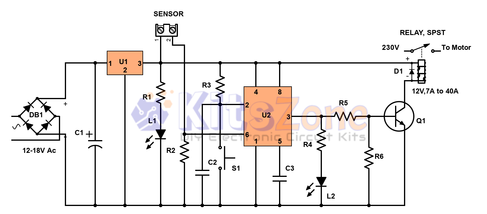
Semi-Automatic Water Level Controller Circuit Using 555 Timer
Managing water efficiently is crucial to avoid wastage and overflow 🚰. A semi-automatic water level controller circuit using a 555 timer IC provides a simple yet effective solution for controlling water pumps. This project not only prevents tank overflow but also reduces manual effort. By using a 555…
Continue reading...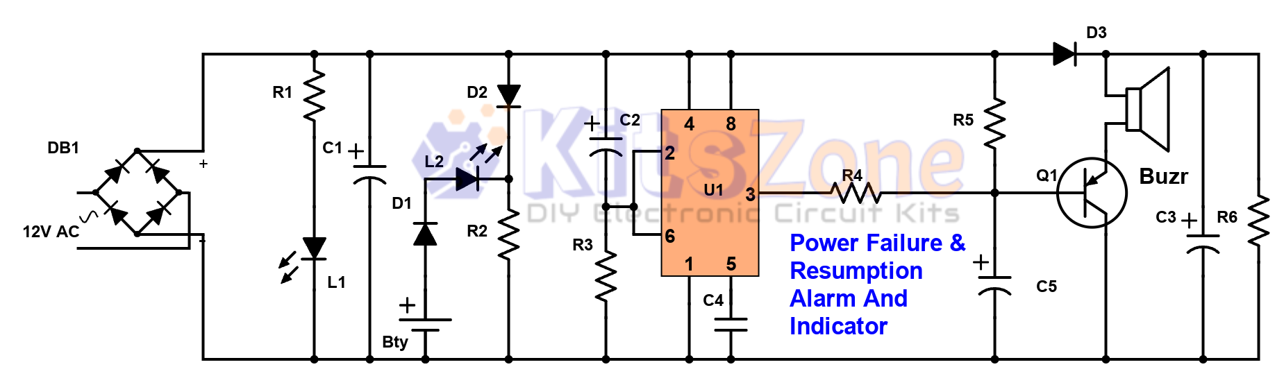
Power Failure and Resumption Alarm Circuit using 555 IC
⚡ Power cuts can cause inconvenience, equipment damage, and even safety risks. That’s why a Power Failure and Resumption Alarm Circuit using 555 Timer IC is a simple yet powerful solution! This DIY electronics project not only alerts you when electricity goes off but also notifies you…
Continue reading...