Full And Low Water Tank Alarm Circuit With A Push Switch To Turn Off The Alarm
Can be used commercially or as project
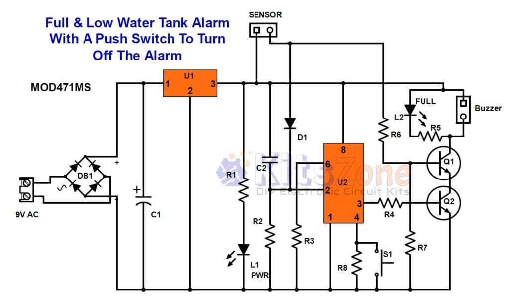
The circuit I previously shared (click here to view), while functional, presents a significant drawback: it requires manual intervention to turn off the device upon hearing an alarm indicating that the tank is either full or low. This necessitates the user to manually switch the device back on to continue monitoring the levels, resulting in a cumbersome and time-consuming process. However, the upgraded circuit design outlined below addresses these issues by eliminating the need for constant user involvement. It can remain powered on continuously, allowing for seamless and uninterrupted level monitoring. Furthermore, the alarm can be conveniently turned off with a simple push of a momentary switch, enhancing both user experience and operational efficiency.
Circuit Diagram

Parts Required
DB1 – W04 or Db107 (Bridge Rectifier)
9V AC – Step Down Transformer, 200 to 500mA
Note: We can use a 12v to 18v Step-down transformer if 7812 is used otherwise it will damage the timer IC. If 12V SMPS power supply is used, there is no need of 7812.
Capacitor:
C1 – 220uf / 40V
C2 – 0.001uF (ceramic or polyester) – 102
Diode:
IN4007
Resistor: (All 1/4W)
R1, R5 – 4.7K
R2, R3 – 470K
R4, R6 – 2.2K
R7 – 22K
R8 – 33K
Transistor:
Q1, Q2 – BC547
Buz – 3v to 24V DC buzzer (continuous or intermittent)
Led – 3mm 0r 5mm
L1 – Green
L2 – Red
S1 – Normally Open Momentary Switch
Sensor – Contact type metal sensor and a normally closed magnetic float switch. Both are connected parallel to the sensor terminals. Metal sensor is used to detect the full level and float switch is used to detect the low level.
Integrated Circuit:
U1 – 7812
U2 – 555 Timer IC
Prototype
Circuit Working
This circuit produces an audible alarm when the water level in a rain or water tank rises above a preset level and overflows. It will sound an alarm whenever the water level reaches the top position in the overhead tank, thus it alerts one to turn off the motor to prevent water wastage. It can also work as a low tank alarm if a normally closed magnetic float switch is connected to the sensor terminal.
The purpose of this circuit is to detect when there is an overflow of water in a tank and stop it from continuing to rise which would cause flooding. This can be useful in many different places where there are tanks of water like swimming pools, fountains or overhead tanks for example.Apart from a full tank alarm, it alerts the user whenever the water level falls below a preset level in the water tank so that there won’t be any shortage of water.
It has a power indicator and a full/low tank led indicator apart from the alarm. The power to this device can be kept “on” all the time (24 X 7). We can turn off the alarm sound by pressing the momentary switch. We can use contact type sensors and a normally closed float switches to sense the water level inside the tank. We can use this circuit in the overhead tank, swimming pools, underground sump, aquariums, etc.. in order to monitor the top and low level.
This circuit can be powered by a 9v step-down transformer of current rating ranging from 200mA to 500mA or a 12v regulated power supply like SMPS. We can use speaker wire to connect the device to the sensor or float switches inside the tank. For alarm, here I have used a continuous tone buzzer. We can also use musical buzzer or a recordable chip with a slight modification in the circuit.
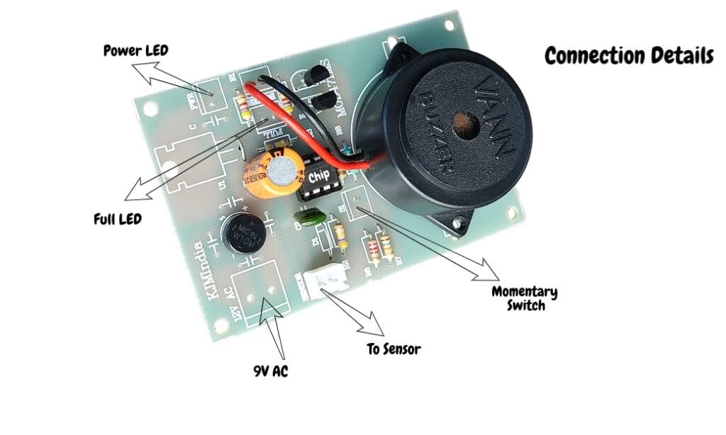
Circuit Board
Circuit Board Connection


![[Multi-Colour] Automatic Night Lamp Circuit Diagram Using LDR And CD4017 | Kitszone.com](https://kitszone.com/wp-content/uploads/2024/11/Automatic-multicolour-night-light-circuit-390x220.jpg)


One Comment