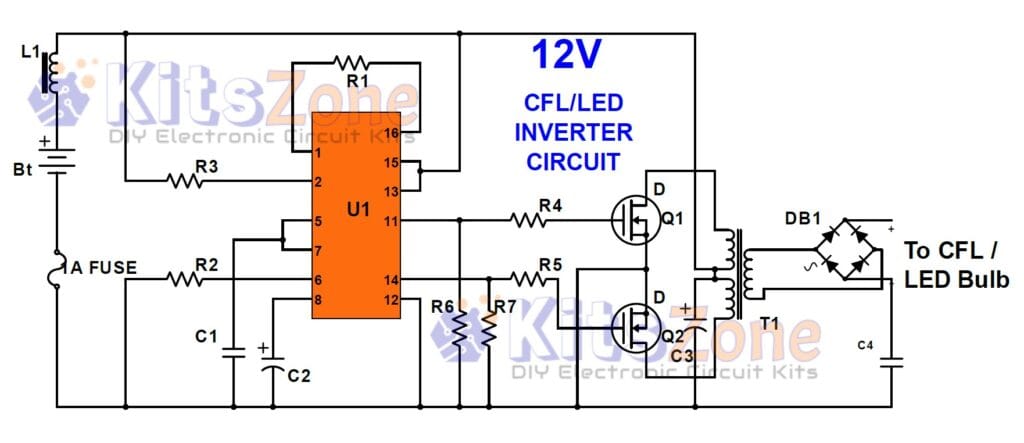
This circuit is designed to run any regular CFL or LED bulbs up to 32 watts. You can try using a higher wattage bulb or changing the transformer. The battery to be used is 12 volts. The output of this circuit is fed to the transformer through two MOSFETs. This circuit is very simple and does not require any special components. It is easy to understand and build.
Circuit Diagram
Parts Required
Resistor(1/4W):
R1- 4.7K
R2- 18K
R3- 4.7K
R4- 22E
R5- 22E
R6- 10K
R7- 10K
Capacitor:
C1- 0.001 uF (102)
C2- 100uF/25V
C3- 4.7 uF/25V
C4- 0.001 uF (102) 1Kv
Others:
U1- SG3525A
L1- Choke(100 uH, 1A)
T1 – Ferrite Transformer (EE28)
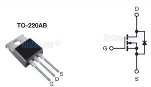
MOSFET (Q1 & Q2) – IRF540/ IRFZ44/ P55NF06
Diode(BR) – D1-D4 – BA159
Fuse (F1) – 1A
Battery – 12V or Two 6V Battery in series or Three 4V battery in series. We can increase the backup duration by using 12v batteries of higher ampere. I have tested this circuit with a lead-acid battery.
SG3525A Pinout
IRFZ44 Pinout
Circuit Working
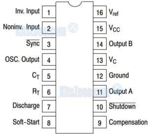
The circuit is pretty simple and is based on an SG3525 controlling pulse width modulator IC that runs a couple of MOSFETs and a push-pull step-up transformer. The capacitor at pin 5 and the resistor at pin 6 set the on-chip frequency. The frequency of the output is cut in half by an internal flip-flop, and the flip-flop’s output drives buffers that can source or sink more than 200mA. The two MOSFETs Q1 and Q2 are driven by the buffer’s output at pins 11 and 14. The high output current is perfect for quickly charging and discharging the MOSFET gate capacitances, which makes for fast switching times. This means that the MOSFETs work well and lose little power. The step up push-pull transformer is powered by MOSFETs. AC energy is sent from the transformer to a bridge rectifier, which turns it into DC voltage. The transformer is connected to a bridge rectifier to convert the AC voltage to DC voltage.
Prototype
Connection Diagram
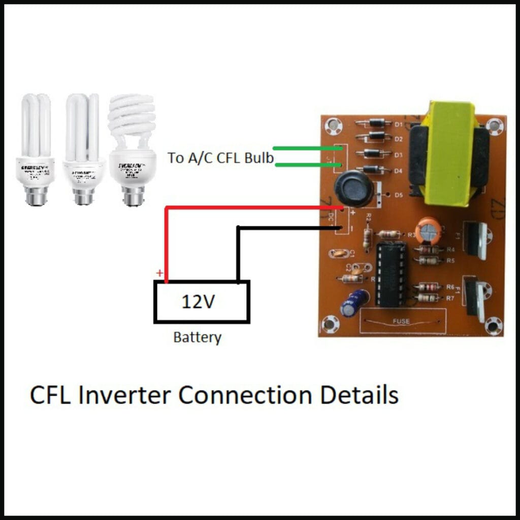
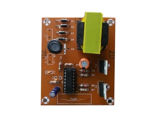
This circuit do not include a charging section. Tested up to 32 Watts cfl/LED bulb without any heat sink. Can also charge mobile or tabs. Requires 12v battery of any ampere. We can also use a computer ups battery.
Caution: The output from this inverter is dangerous. So, handle with care. Never work on the circuit with power applied. The finished project should be installed in a plastic box.


