Water Level Indicator Circuit With Dry Run Alarm
Author: Manikandan K J
Introducing the Water Level Indicator Circuit Project, ingeniously designed with the incorporation of an IC 555 chip, featuring Motor Dry Run Alarm for an advanced monitoring solution. This versatile circuit can be easily adapted to serve as a low tank alarm by simply utilizing the dry run sensor as a low tank sensor. However, it's important to note that this configuration provides a singular tone alert for both tank-full and tank-low conditions.
Circuit Diagram:
Parts Required:
Resistors (All 1/4W)
R1 – R6 – 1M
R7 – R12 – 220K
R13 – R17 – 1K
R18 – 3.3K
R19 – 1M
R20 – 100K (Preset)
R21 – 1K
R22 – 1.5K
Capacitors:
104(0.1uF) – Ceramic Disc – 1 no.
100uF,25V – 1 no.
470uF,40V – 1 no.
IC:
U1- CD4049 (with Base)
U2-555(with Base)
Diodes:
D1 – LED
D2 & D3- IN4148
DB1- W04 (Bridge Rectifier)
Transistor:
S8550 PNP
Relimate Connector:
Sensor – 8 Pin (Male + Female + Wire) [Optional]
Led(-) – 6 pin (Male + Female + Wire) [Optional]
Transformer:
9v ,500 – 1000mA
Please note: If you use 7812(U3), we can use 15v or 18v stepdown transformer
Others:
2 pin Terminal Block Connector
12V DC Buzzer
Features of this circuit:
- Lоw Cоѕt
- Low Power Cоnѕumрtіоn
- Moderate electrolysis
- Easily Sеrvісеаblе
- Built Using Readily Available Cоmроnеntѕ
- Nо Mісrо-соntrоllеrѕ аrе used, so no programming knowledge rеԛuіrеd.
- 6 Lеvеlѕ оf Indication (3,4,5 Lеvеlѕ іѕ аlѕо роѕѕіblе)
- Sоundѕ аn аlаrm when the water rеасhеѕ tор lеvеl
- Sounds аn alarm when thеrе is no flоw оf wаtеr іntо thе tаnk
- Sоundѕ аn alarm when the water flоw ѕtорѕ in thе middle
- Sоundѕ аn аlаrm when there is no water in thе ѕumр/wеll thuѕ protecting the mоtоr.
- Can also indicate water low level if flow feature is not used.
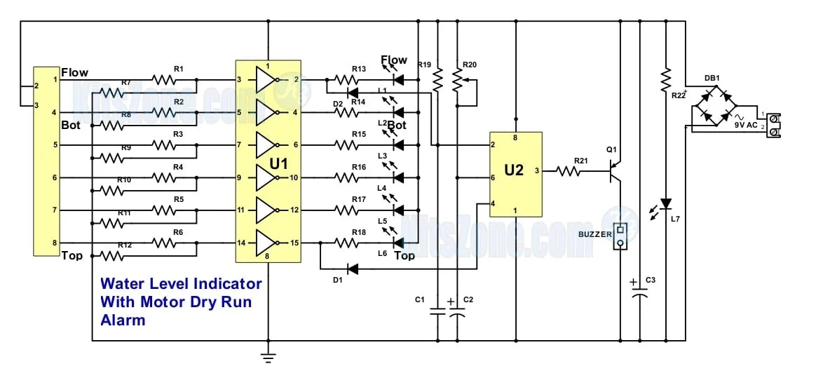
Circuit Working:
The circuit comprises of CMOS hex-inverter IC and the famous timer IC. Bridge rectifier (B1) is used to convert AC to DC.Let us assume that the tank is empty. On switching on the circuit, it will wait for few seconds to sense the flow of water into the tank by the sensor that is fitted on the water inlet pipe.
If there is no flow of water into the tank after few seconds (which is set by adjusting the preset R20), the circuit will sound an alarm indicating that there is no flow of water ( the reason may be: there is no water in the sump/well or the motor is not running.).
If the sensor senses the flow of water, you will not hear the alarm until it reaches the top-level set by you. If the water flow stops in the middle, it will alert you by sounding an alarm.
Timer IC in the circuit is used to perform the above function. When the water in the tank touches each sensor, the concerned LED will light up. When the water reaches the top level, it will sound an alarm alerting us to switch OFF the motor.
D2 And D3 are used to pass only the negative pulses for triggering the timer. R13 to R18 resistors are used to limit the current flowing through the LED. We can use either 9v or 12v, 500mA step down transformer to power the circuit.
F[L] in the sensor can be used as the flow or low-level sensing. Similarly, F[L] in the led (-) can be used to indicate water flow or low level respectively.
After assembling the components on to the circuit board, you can use any plastic container in order to fit this kit. I have used a snack box to fit it. It is readily available in almost all supermarkets.
We can use this circuit in different modes: 1) As overflow indicator alone 2) As overflow and low-level indicator. 3) As 3,4,5,6 level indicator. 4) As water flow alarm etc., A single kit for multiple uses.
Working Video:
Frequently Aѕkеd Quеѕtіоnѕ: (FAQ)
Q: Cаn I dіѕаblе the water flоw indicator fеаturе in thіѕ kіt?
Yеѕ.Juѕt remove thе рrеѕеt frоm thе kіt or Shоrt 1 and 2 (ѕеnѕоr)
Q: Is it possible to stop the alarm after some time?
Yes. It is possible by using the circuit below.
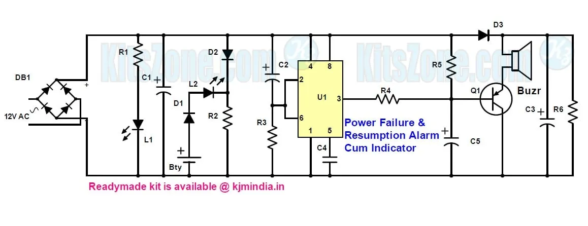
Auto Cut-off for Overflow Alarm:
The circuit shown in the presentation will sound an alarm endlessly until the circuit is switched off. The circuit shown at the top of this page is used to cut off the alarm automatically after a few seconds or minutes. Alarm “ON” time can be set by adjusting the preset 1M. Instead of connecting the buzzer directly to the output, it can be connected via the circuit shown at the top. Connect the positive wire (brown wire) to +P and negative wire to -P (black wire)
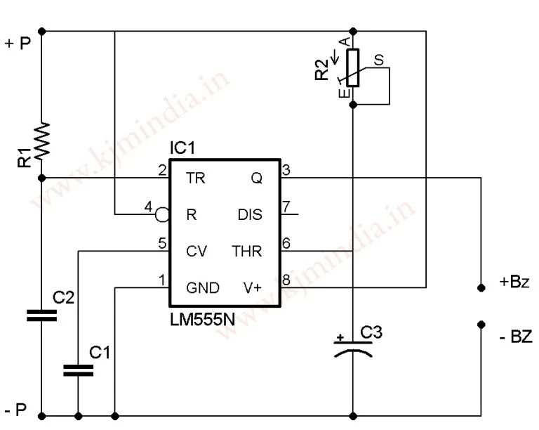
Components Dеtаіlѕ for auto alarm cut-off:
Cарасіtоr:
C1 & C2 – 0.1uF(ceramic)
C3 – 100uF
Resistor:(1/4W)
R1 – 1M
R2 – 1M(рrеѕеt)
IC – 555 Tіmеr ic
Buzzеr – 12V DC
General purpose PCB
Q:Can I convert this indicator to a controller?
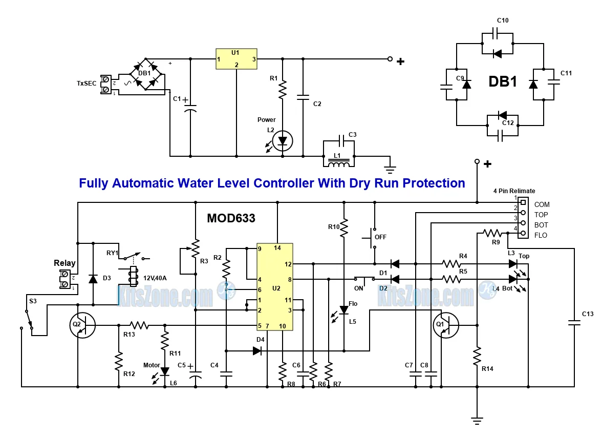
Yes. With a slight modification, we can convert this indicator to a water level controller.
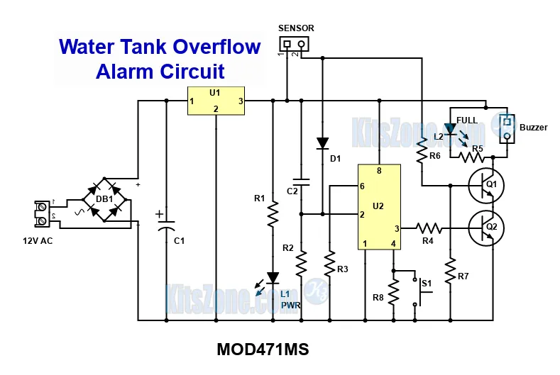
Here is the circuit of a semi-automatic water level controller:

This is a semi-automatic water level controller. If you need a fully automatic circuit, please click here. Remove the buzzer from the water level indicator board and connect the transistor’s collector to this input as shown in the above circuit diagram. Momentary switch S1 is used to start the pump. Once the water reaches the top level or if the water flow stops in the middle, the pump will stop automatically. As it has only a few components, this circuit can be easily assembled on a general-purpose PCB.
Parts required for semi-automatic controller:
Resistors(1/4W):
R1 – 1k
R2 – 100k
R3 – 100k
R4 – 1k
Capacitors:
C1 – 0.01uF
C2 – 10uF/25V
Transistor:
8050 NPN Transistor
S1: Momentary Push to on switch
IC : 555 Timer
Relay: 12V, 20A or 30A Based on your requirement
General purpose PCB
Placing the probes:
You can use thick stainless steel/aluminium or copper wires as sensors or a float switch. We can also use stainless steel bolt & nut, keys, spoons, etc. as sensors. As electrolysis is not a big issue for me, I have used thick copper wires. We have to clean the wire once a year to remove the dirt deposited on the wire. Please ensure that the sensors do not touch each other or the sides or bottom of the water tank. Shown below is a demo tank made out of disposed material.

Connection Details Of 6 Led Water Level Indicator

SENSOR
1 – F(L) – Used for water flow sensing
2 – +ve supply – Used for water flow sensing
3 – +ve supply – Kept inside the tank but should not touch the bottom of the tank.
4 – First Level
5 – Second Level
6 – Third Level
7 – Fourth Level
8 – Top Level
Both 1 and 2 are used for water flow sensing in the OHT or low water level sensing inside the sump.
LED- should be connected to the negative terminals of the 6 LEDs.
LED+ should be connected to the positive terminals of the 6 LEDs. All +ve terminals should be shorted together.
Preset should be adjusted for the wait time as per your requirement.
Buzzer should be connected with the correct polarity. Brown wire(+) and black wire (-)
Use 9v,500mA – 1A step-down transformer. We can also use 15v transformer. In this case, we have to use 7812 regulator ic in the U3 slot on the board.
We can use 8 colour flat ribbon wire/Cat-6 wire to connect the sensor in the tank to the indicator unit.
For sensor, we can use thick copper wire/aluminium/steel wires or magnetic float switches.
LED Details:
Green colour LED can be used as power indicator.
Red can be used to indicate top level
Tricolour LED can be used to indicate the water flow
White colour LED can be used to indicate other levels.