Low Battery Level Monitor Using Op-Amp 741
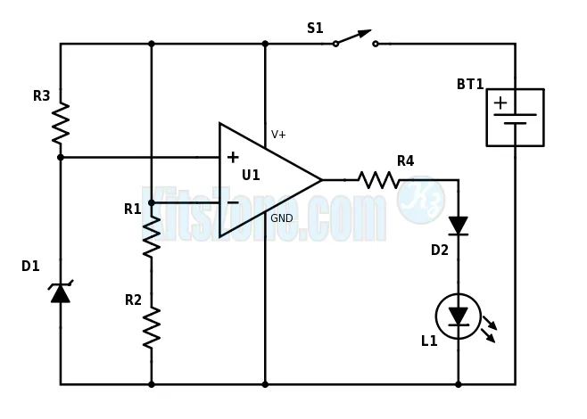
Circuit Diagram
Parts Required
Resistors: (All are 1/4 Watts)
R1 – 1M
R2 – 470K
R3 – 8.2K
R4 – 680E
Diodes:
D1 – 5.1 Zener (500mW)
D2 – IN4148
L1 – LED (any color)
IC:
U1 – Op-Amp 741
Battery:
BT1 – 12V
Switch – On/Off
Circuit Working
A 741 op-amp is employed as a voltage comparator. The non inverting input is connected to zener reference source. Reference volt is 5.1V. R2 is adjusted so that the voltage at the inverting input is half the supply voltage. When the supply voltage i greater than 10.2V, the LED will not light. When the supply falls just below the 10.2V, the IC’s inverting input will be slightly negative of the non inverting input and the output will swing fully positive. The LED will light, indicating that the supply voltage has fallen to the preset threshold level. The LED can be made to light at other voltages by adjusting the resistor R2.