Fully Automatic Water Level Controller Circuit With Motor Dry Run Protection Without Using Microcontroller
Author: Manikandan KJ
Automatic water level controllers regulate the water supply for a given reservoir/tank to maintain a minimum water level. This water level controller circuit uses a float switch to control the water level of the storage tank. It is an automatic system, so it will start to fill up when the height of the water goes below a certain point. If it reaches full capacity, the float switch will automatically turn off. This protects against overfilling and spilling of water. The water level controller manages the level of water in a tank. It automatically detects the tank's water level and turns the pump on or off to maintain it at the desired level. The float switch helps detect different levels of water by using a magnetic switch module that floats on top of the water.
Features: (Click here to buy this kit)
- Low-cost circuit made out of readily available components.
- Low power consumption.
- Turns on the pump when the level of water goes below bottom level.
- Turns off the motor when the water reaches the top level.
- Turns off the motor when there is no water in the sump or well.
- When power fails and resumes later if the water level is below the bottom, it will automatically turn on the pump.
- Motor dry run protection.
- Compact size
- Can be used for motors up to 3HP power.
- Fully automatic control. Manual on and off switches are also provided.
- Semi On and Off option available. (Can be used as a semi-automatic controller too)
- Top, Bottom, Flow, Power and Motor On indicator LED
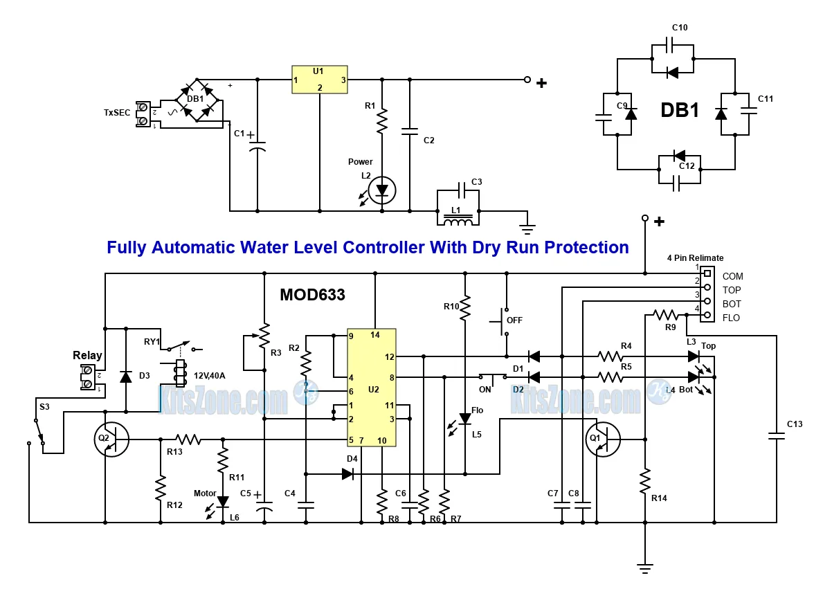
Circuit Diagram
Parts Required (Click here to buy the ready-made kit)
Resistors (All are 1/4 watts)
R1,R4,R5,R10,R11 - 4.7K
R9,R13 - 2.2K
R3 - 1M Preset
R2, R14 - 10K
R6, R7 - 470K
R8 - 33K
R12 - 18K
Capacitors
C1 and C5 - 100uF,50V
C2, C3, C4, C7, C8, C13 - 0.1uF disc (104)
C6 - 0.01uF disc (103)
Inductor
L1 - 100uH, 1A
LEDs (3mm or 5mm as per your choice)
L2 - Power
L3 - Top
L4 - Bottom
L5 - Flow
L6 - Motor
There is no L1
Diodes
D1,D2 And D4 - IN4148
D3 - IN4007
Bridge Rectifier DB1 - W04
Transistor
Q1 - BC547
Q2 - 2N2222
IC
U1 - 7812 with T220 heat sink
U2 - 556 Dual Timer
Relay: 12V, 30A or 40A
Transformer: 12V, 15V or 18V/ 1Ampere
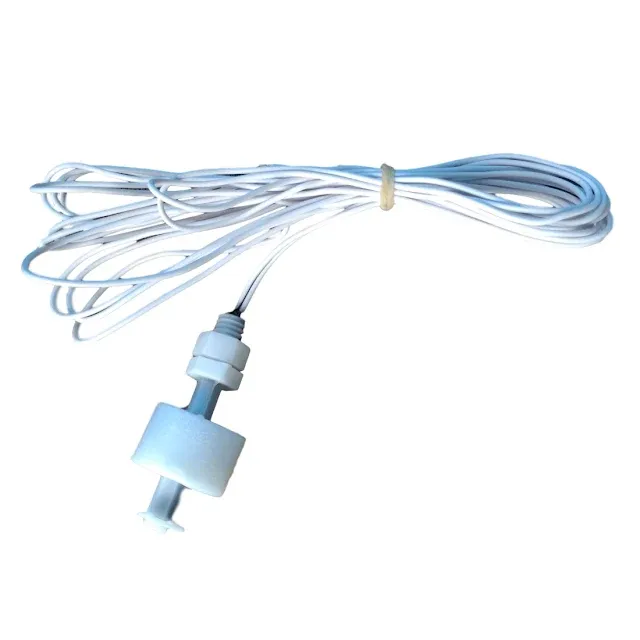
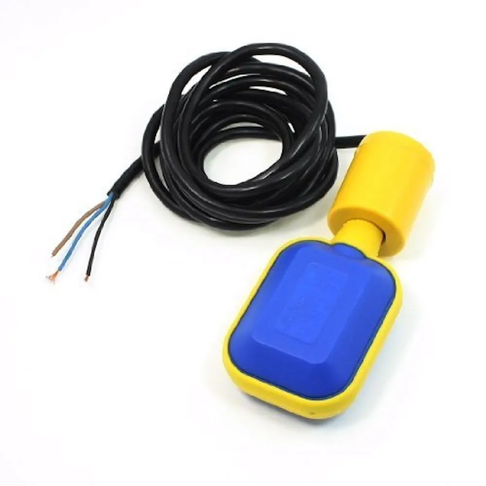
Float Switch to be used: Vertical or Horizontal
Circuit Working (Click here to buy the ready-made kit)
The AC voltage from the stepdown transformer (12V, 15V or 18V can be used) is fed to the bridge rectifier (DB1) in order to get a DC volt. The output DC is filtered by capacitor C1. It is fed to the input of the regulator U1. The negative of the output volt is connected to the L1 and C3 to avoid line disturbances. The DB1 shown in the image is optional. The heart of the circuit is the dual timer IC U2. The trigger and threshold pins 8 and 12 detect the low and high levels of water in the tank. The reset pin 4 and output pin 9 are connected together. Transistor Q1 is used to detect the water flow. The collector of the transistor Q1 is connected to the trigger pin 6 of U2 through a diode D4. The output pin 5 of U2 is fed to the base of the NPN transistor Q1 through a resistor R13. The push button switch ON is a normally closed type used here to turn on the pump. Once activated, the pump will be turned off by pressing OFF switch which is normally open type or when the water level touches the top float or water flow stops in the middle.
Once the unit is powered on, LEDs L2 and L6 will be turned On and the relay gets activated. Once the relay is activated, it will wait for a few seconds and checks whether the water is flowing into the tank or not. The wait time can be adjusted by the preset R3. If there is no flow of water, it will automatically turn off the pump. In this scenario, we have to turn off the device and turn it ON once the issue is sorted out. If the water continues to flow, the relay will remain activated until it reaches the top float or the OFF-push button is pressed.
We can turn on and turn off the pump using the ON and OFF push button switches provided the water level is between the bottom and top level. Manual/Auto switch option is available in this circuit. It is achieved by directly connecting to the relay bypassing the circuit. We can also connect a Manual/Auto switch externally bypassing the relay. This circuit is 100% safe and corrosion proof as it uses magnetic float switches. We can give a minimum 2 years guaranty for controllers using this circuit. As the components are readily available in the market, we can easily build this circuit. I have been using this circuit for more than 6 years!
Please ensure that you are using good quality float switches. With a slight modification in the external connection, this circuit can be used as a semi - automatic water level controller too!
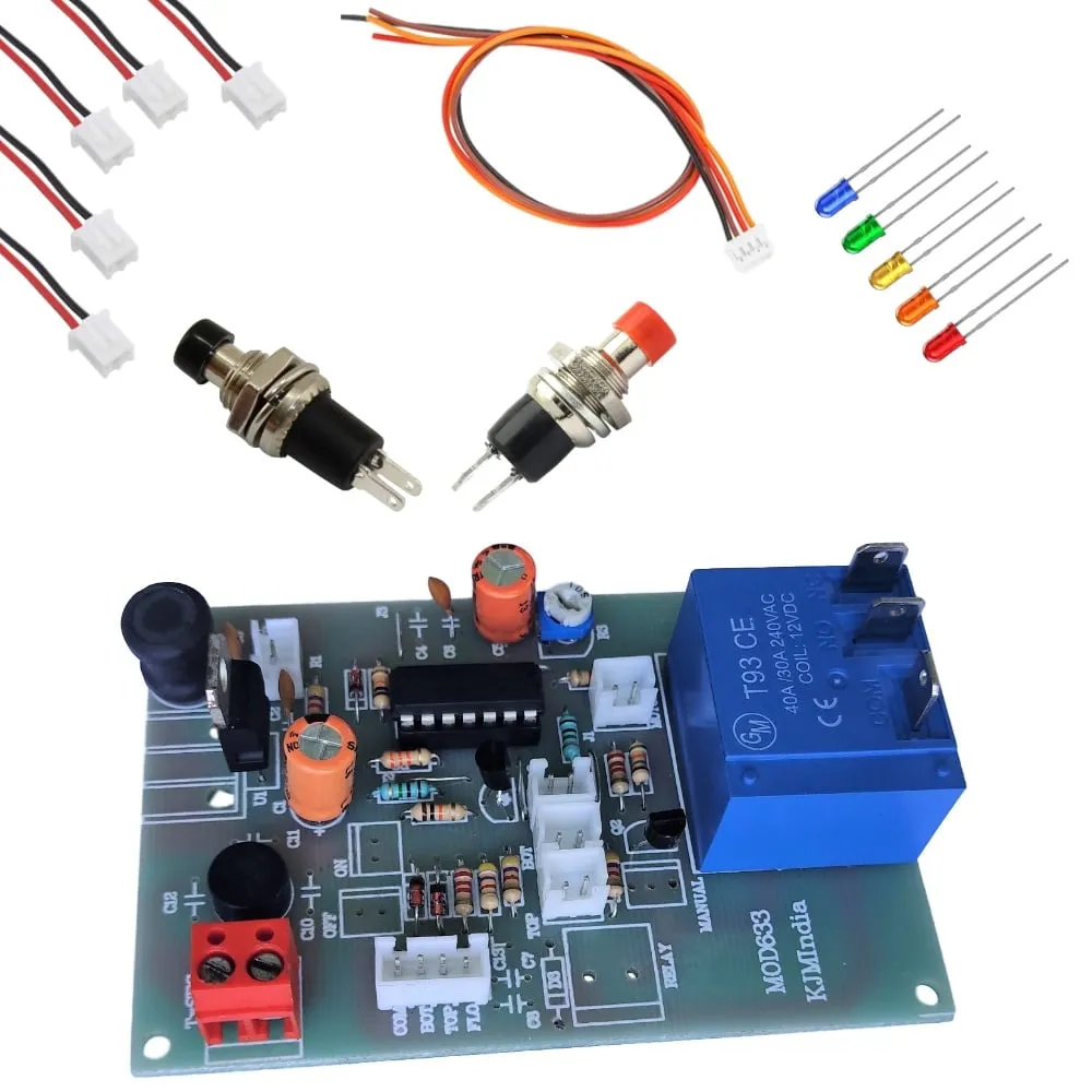
Water Level Controller Readymade Kit
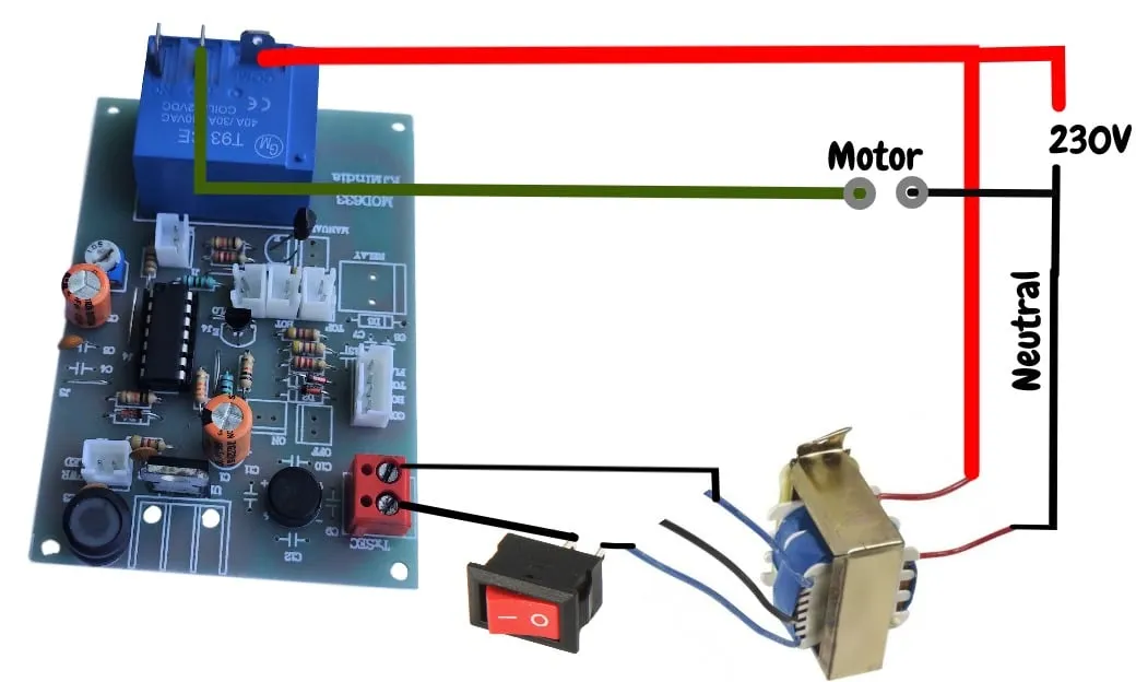
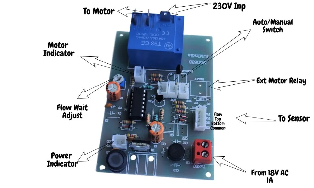
Water Level Controller Module Connection Details
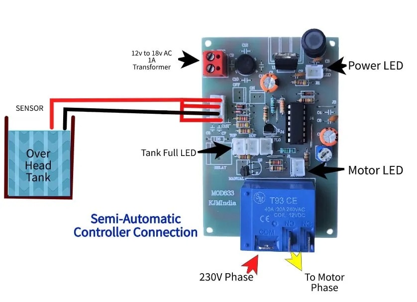
Semi-automatic Controller Connection Details
Same board can be used as a semi-automatic water level controller with or without dry run protection feature. In this case, we can use only the SS metal sensors instead of a float switch.
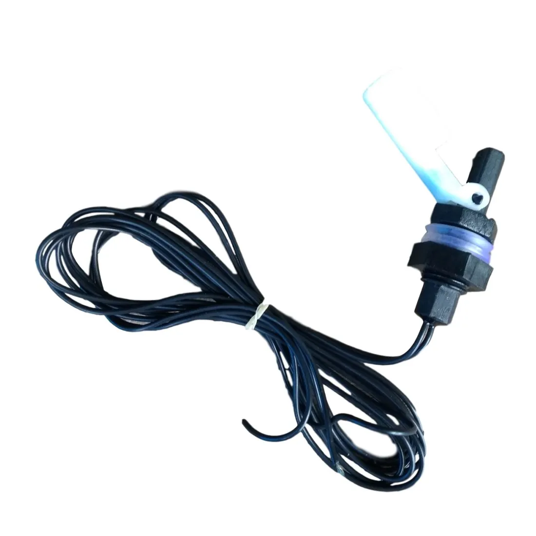
Use Any Of The Following Float Switches
Horizontal Magnetic Float
Vertical Magnetic Float
230V Cable Float
Top and Bottom are shorted. One terminal of float switch is connected to the shorted terminal and another one is connected to the common.
In this case, either the top or bottom LED indicator will work.
Connection details of sensor
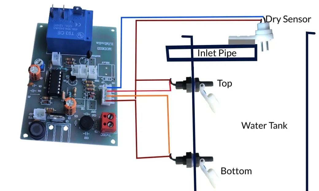
Power and Relay Connection details: