Burglar Alarm Using NPN(BC548)And PNP(SK100) Transistor
The burglar alarm circuit shown here sounds an alarm when the wire loop is broken.The system is implemented by installing a sensing loop, which is basically a thin copper wire. This way, the loop is both invisible and brittle enough to break easily and initiate the alarm mechanism.
At the time of an intrusion, the loop breaks and this causes the loudspeaker to generate a continuous and loud alarm sound. Once the loop is broken, the alarm can only be silenced by either turning OFF the power supply or by replacing the broken wire by a new continuous loop.
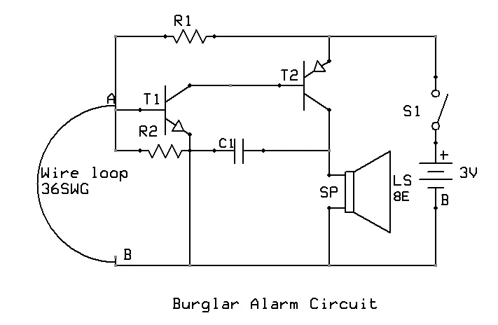
Circuit Diagram
Working Of the Circuit
It consists of an oscillator section which is merely a two-stage amplifier with feedback. This amplifier is implemented with the help of two transistors (T1 is an NPN transistor-BC548 while T2 is a PNP transistor-SK100) connected in a feedback arrangement to generate oscillations. Transistor T1 is responsible for generating oscillations while transistor T2 (connected to the base of T1) amplifies these oscillations in order to drive the loudspeaker for sounding the alarm.
Consider the following cases:
Secure Premises: The connection of the two transistors is such that the base of T1 is normally shorted to the ground and that it remains in the cut-off mode when the sensing loop is intact. Due to the absence of the base current in T1 in this mode, there are no oscillations and hence, the loudspeaker does not generate the alarm sound. This indicates that no intrusion has taken place.
Intrusion: When the loop is broken by an intruder or a burglar, the base of transistor T1 becomes open and oscillations are generated at its collector. As the base of T2 is connected to the collector of T1, the oscillations are amplified by it and further fed back to its emitter (via the path along capacitor C1 and resistors R1, R2).
The loudspeaker obtains this amplified signal from the collector of transistor T2 and converts it into audible alarm sound. This indicates the occurrence of an intrusion/break-in.
As both the transistors are silicon type, the current drawn by the circuit is very low even in the alert mode.
Parts Required
Semiconductors:
T1 - Transistor BC548
T2 - Transistor SK100
Resistors(all 1/4W, ±5% carbon):
R1 - 270 Kilo- ohm
R2 - 10 Kilo-ohm
Capacitors:
C1 - 0.1μF,Ceramic disk
Miscellaneous:
S1 - SPDT Toggle(On/Off) Switch
LS - 4 or 8Ohm,1Watt Loudspeaker
Battery Holder