20 Led Chaser Circuit Without Ic 555 | How To Build A Light Chaser Circuit Using Cd4017 And Cd4013
This is a simple 20 led chaser circuit built using the decade counter ic CD4017 and Dual flip flop ic CD4013.
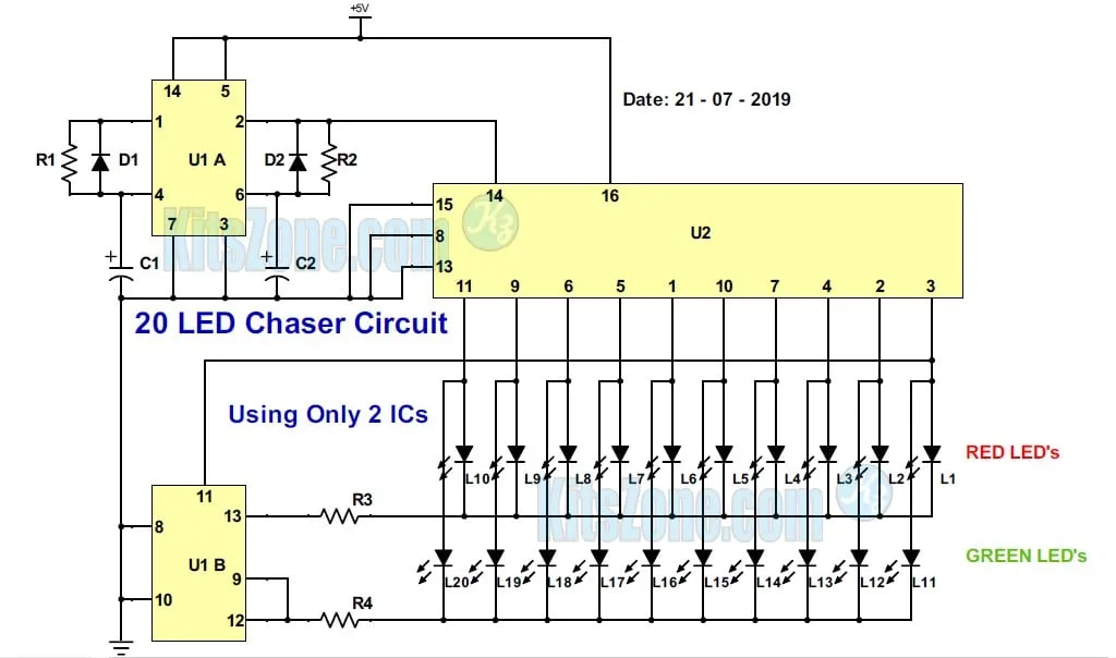
Circuit Diagram
Parts Required
Resistors: (1/4W)
R1 & R2 – 6.8K
R3 & R4 – 4.7K
Capacitors:
C1 & C2 – 100uF (For more speed, reduce the value)
Diode
D1 & D2 -IN4148
IC
U1 – Dual Flip-flop CD4013
U2 – Decade Counter CD4017
LEDs
L1 – L20 – Any Colour
Power supply: 5V to 12V DC
General purpose PCB or Breadboard
Circuit Working
CD4017 is wired as divide by 10 counter. One flip-flop of CD4013 is wired as multivibrator and another flip flop is wired as divide by 2 counter.
Output pin 2 from CD4013 is connected to the input 14 of CD4017. Pin 3 of decade counter is connected to the pin 11 of the dual flip flop ic. Output pins 12 and 13 are connected to the negative terminals of Leds. That is negative terminal of L1-L10 is connected to the 13th pin of U1 and L11-L20 is connected to the 12th pin of U1.
11th pin of U1 is triggered by 3rd pin of U2. That is, once it completes one cycle (3 to 11 of U1), it triggers the 11th pin of U2. This cycle repeats until the power is removed.
Working Video